Device for the aftertreatment of exhaust gas from a motor vehicle

Active Publication Date: 2016-09-15
MAN NUTZFAHRZEUGE AG
View PDF3 Cites 19 Cited by
  • Summary
  • Abstract
  • Description
  • Claims
  • Application Information

AI Technical Summary

Benefits of technology

[0037]It is possible to leave an annular gap between the mixing device and the interm

Problems solved by technology

One disadvantage to this is that the exhaust gas flow in the mixing tube deviates from a rota

Method used


Image

  • Device for the aftertreatment of exhaust gas from a motor vehicle
  • Device for the aftertreatment of exhaust gas from a motor vehicle
  • Device for the aftertreatment of exhaust gas from a motor vehicle

Examples


Embodiment Construction

[0063]In The embodiments described with reference to the figures partially correspond, so that similar or identical parts are provided with the same reference numerals and are also explained by reference to the description of the other embodiments or figures, in order to avoid repetition.

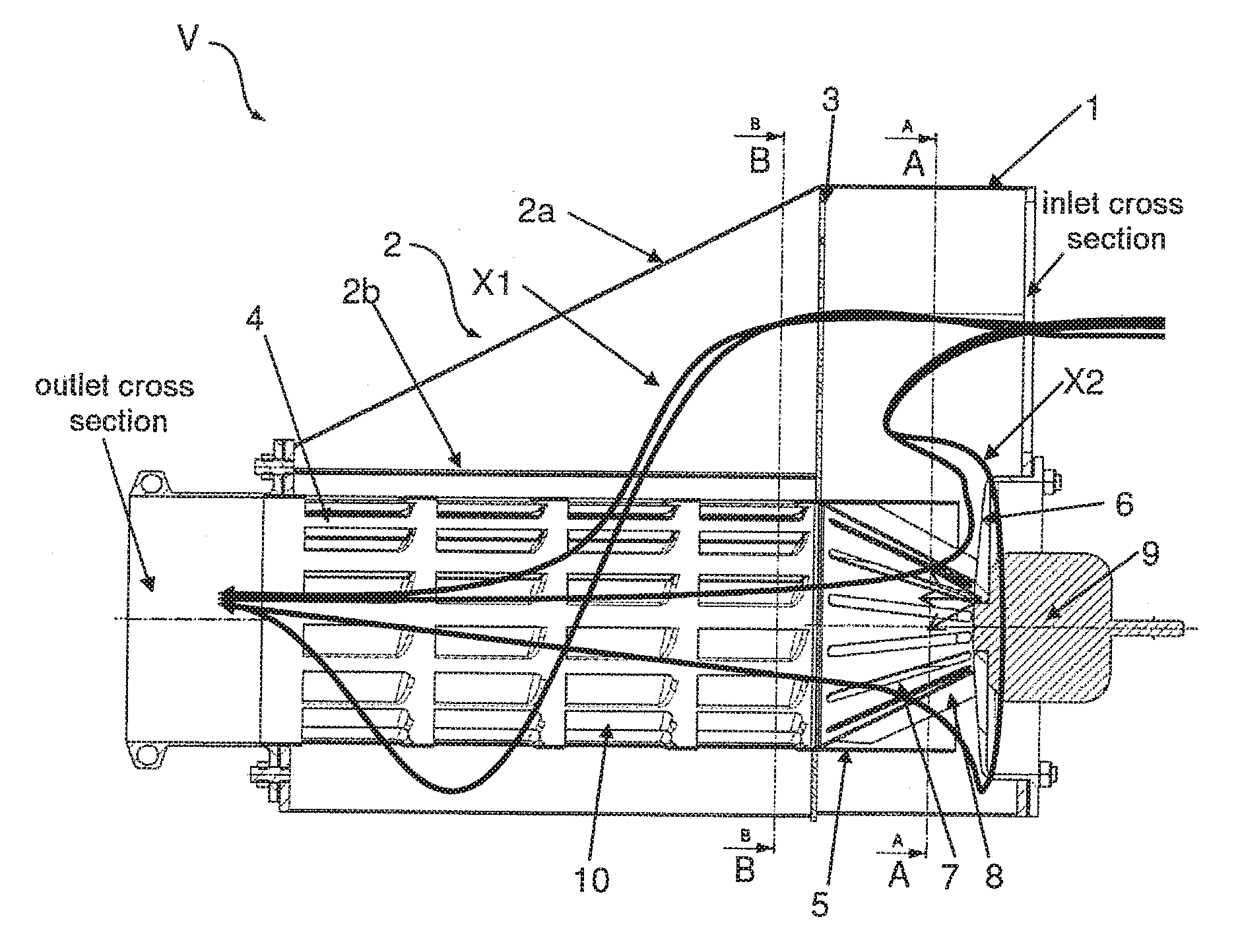
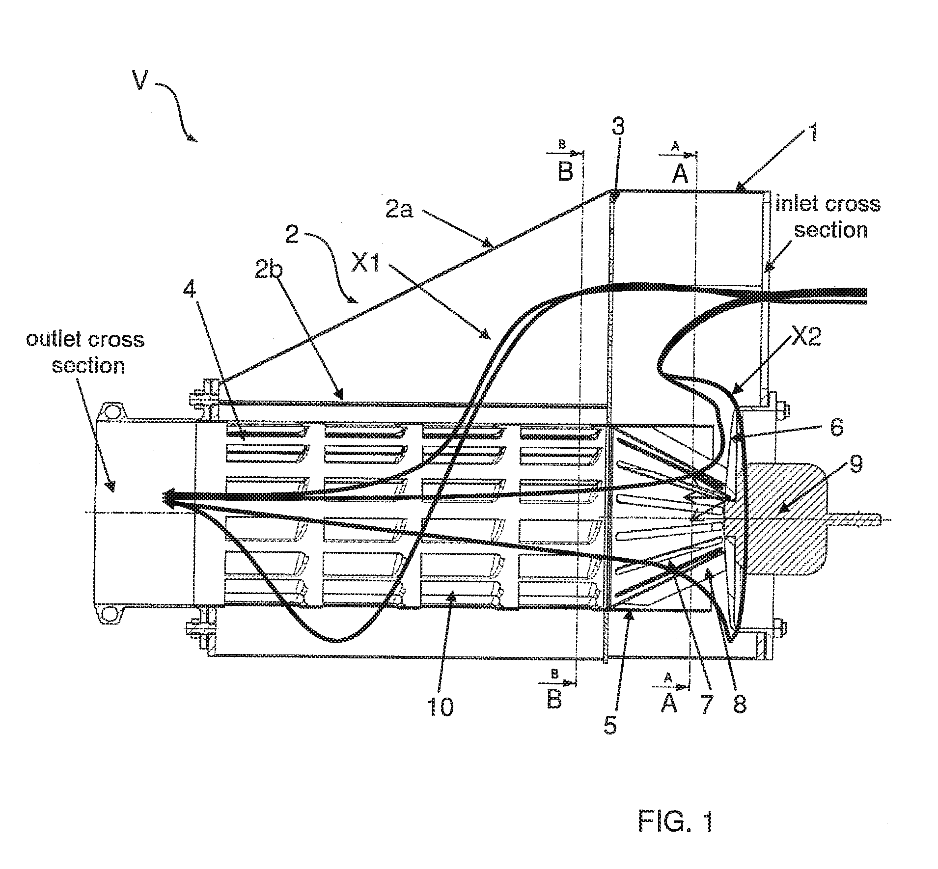
[0064]FIG. 1 shows a device V for the aftertreatment of exhaust gas from an internal combustion engine, preferably by mixing the exhaust gas with an at least partially liquid additive (for example an aqueous urea solution) introduced by metered addition, evaporation of the liquid fraction of the additive and preparation of the exhaust gas-additive mixture for a downstream catalytic converter.

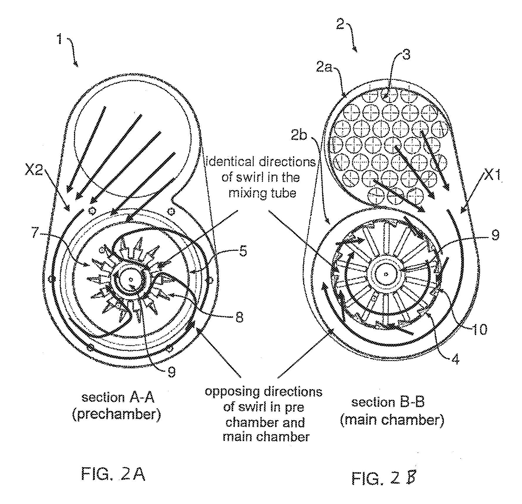
[0065]The device V comprises, in particular, a prechamber 1, a main chamber 2, a perforated separating device 3 (dividing wall), a mixing device 4 (mixing tube) and an intermediate device 7 (nozzle cage).

[0066]The prechamber 1 and the main chamber 2 are connected to one another firstly via the perforated dividin...


PUM


Abstract

A device for aftertreatment of exhaust gas includes: a prechamber having an exhaust gas inlet; a main chamber; a mixing device, in which the exhaust is mixable with an additive; and an intermediate device, via which a partial exhaust gas flow is deliverable from the prechamber to the mixing device. The intermediate device has swirl elements configured to reverse the direction of swirl of swirled exhaust gas flow generated in the prechamber as the exhaust gas overflows into the interior of the intermediate device, and/or the prechamber is configured to impel a first partial exhaust gas flow in a direction of swirl, and the main chamber is configured to impel a second partial exhaust gas flow from the prechamber in a direction of swirl, the direction of swirl of the exhaust gas in the prechamber being opposed to the direction of swirl of the exhaust gas in the main chamber.

Description

BACKGROUND OF THE INVENTION[0001]1. Field of the Invention[0002]The invention relates to a device for the aftertreatment of exhaust gases from an internal combustion engine, preferably of a motor vehicle, in particular a commercial vehicle, for example a heavy goods vehicle or a bus.[0003]2. Description of the Related Art[0004]DE 10 2012 014 334 A1 shows a device for the aftertreatment of exhaust gases from an internal combustion engine of a motor vehicle. The device comprises an exhaust gas inlet pipe, a mixing tube and a spiral housing. A metering device serves for delivering an additive into the mixing tube, wherein the additive should mix as homogeneously as possible with the exhaust gas in the mixing tube. One disadvantage to this is that the exhaust gas flow in the mixing tube deviates from a rotationally symmetrical exhaust gas flow, particularly in proximity to the additive feed device.SUMMARY OF THE INVENTION[0005]An object of the invention is to create an improved and / or a...

Claims


Application Information

Patent Timeline
IPC IPC(8): F01N3/28B01D53/94
CPCF01N3/2892F01N3/2896F01N2610/02F01N2240/20B01D53/94F01N3/0253F01N3/36F01N2470/04F01N2470/18F01N2490/08Y02A50/20B01F23/2132B01F25/102B01F2025/931B01F25/3131F01N3/20
Inventor PUSCHEL, MAXIMILIANALBERT, HERBERT
Owner MAN NUTZFAHRZEUGE AG
Why Eureka
Try Eureka