

Discharge lamp driving device, projector, and discharge lamp driving method
a technology of discharge lamp and driving device, which is applied in the direction of picture reproducers, picture reproducers using projection devices, instruments, etc., can solve the problems of insufficient difficult to form the protruding electrode tip ends of discharge lamps, and difficult to maintain a stable electrode shape. , to achieve the effect of enhancing the service life of discharge lamps
- Summary
- Abstract
- Description
- Claims
- Application Information
AI Technical Summary
Benefits of technology
Problems solved by technology
Method used
Image

Examples
Embodiment Construction
[0049]Hereinafter, a projector according to an embodiment of the invention will be described with reference to the drawings.
[0050]The scope of the invention is not limited to the following embodiments, and can be arbitrarily changed without departing from the technical spirit of the invention. In the drawings described below, for easy understanding of each configuration, there may be cases where the scales and numbers in each structure are different from those of actual structures.
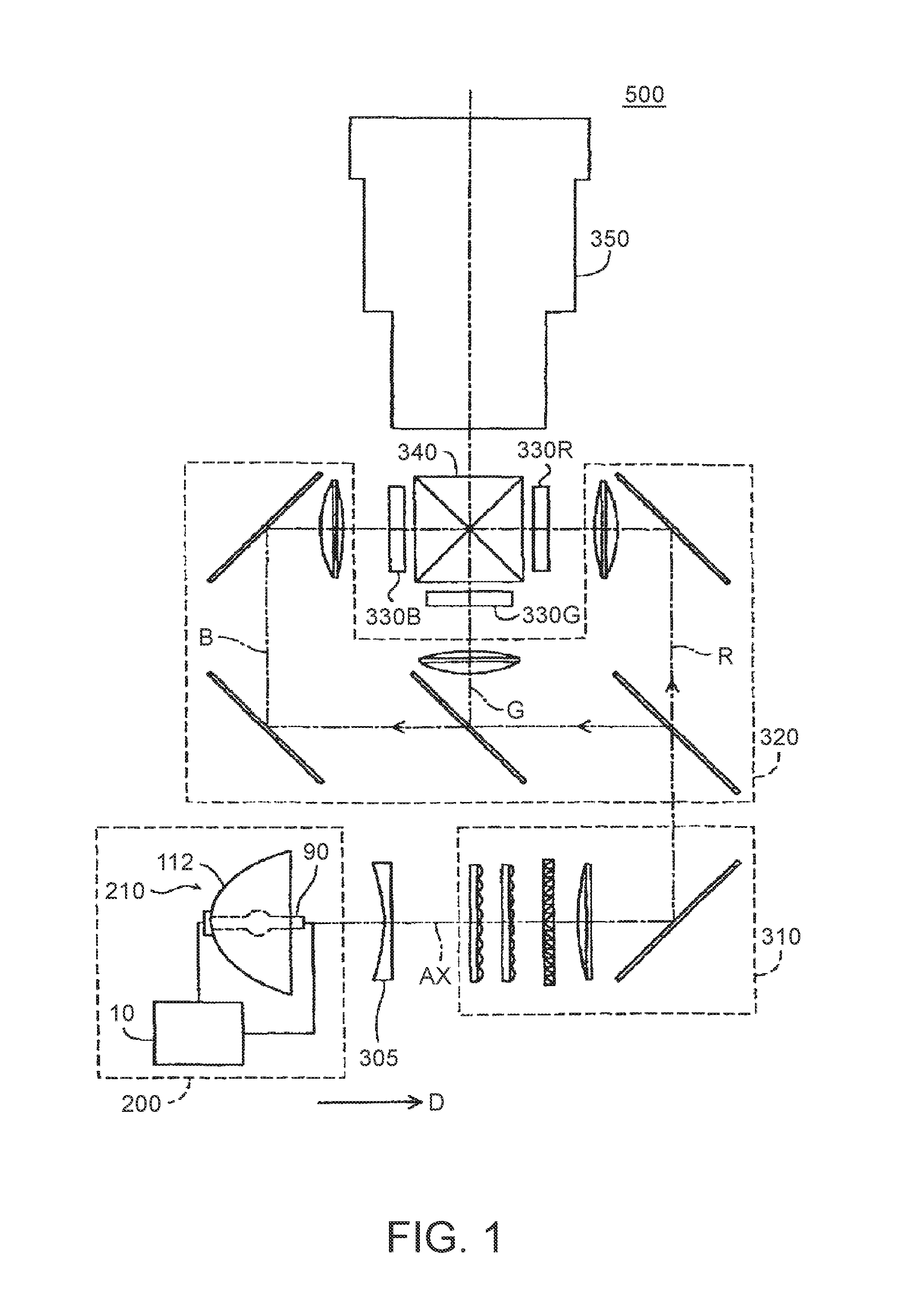
[0051]As illustrated in FIG. 1, a projector 500 of this embodiment includes a light source device 200, a collimating lens 305, an illumination optical system 310, a color separation optical system 320, three liquid crystal light valves (light modulation elements) 330R, 330G, and 330B, a cross dichroic prism 340, and a projection optical system 350.
[0052]Light emitted from the light source device 200 passes through the collimating lens 305 and is incident onto the illumination optical system 310. The collim...
PUM
 Abstract
Description
Claims
Application Information