Connector between two aircraft components, such as a wing and wing tip device

Active Publication Date: 2016-09-22
AIRBUS OPERATIONS LTD
View PDF0 Cites 2 Cited by
  • Summary
  • Abstract
  • Description
  • Claims
  • Application Information

AI Technical Summary

Benefits of technology

The invention provides a connector with moveable spigots that can align with the holes of a component, even if they are not perfectly aligned. The spigots can be re-centered after they are engaged, allowing for changes in the relative positions of the components after connection. This reduces the need for smaller spigots and ensures a tight fit. A re-centering mechanism is used to move the spigots back to their central position. This mechanism includes male and female members with tapered surfaces that push the spigots into a concentric relationship. The spigots tend to resist movement away from the central position, making the connection more secure.

Problems solved by technology

However, the maximum aircraft span is effectively limited by airport operating rules which govern various clearances required when manoeuvring around the airport (such as the span and / or ground clearance required for gate entry and safe taxiway usage).
However, it also results in a relatively loose fit between the spigot and the lug.
A loose fit is undesirable because it could lead to fretting and wear under flight conditions, which often result in the wing / wing tip device vibrating and / or flexing.

Method used


Image

  • Connector between two aircraft components, such as a wing and wing tip device
  • Connector between two aircraft components, such as a wing and wing tip device
  • Connector between two aircraft components, such as a wing and wing tip device

Examples


Embodiment Construction

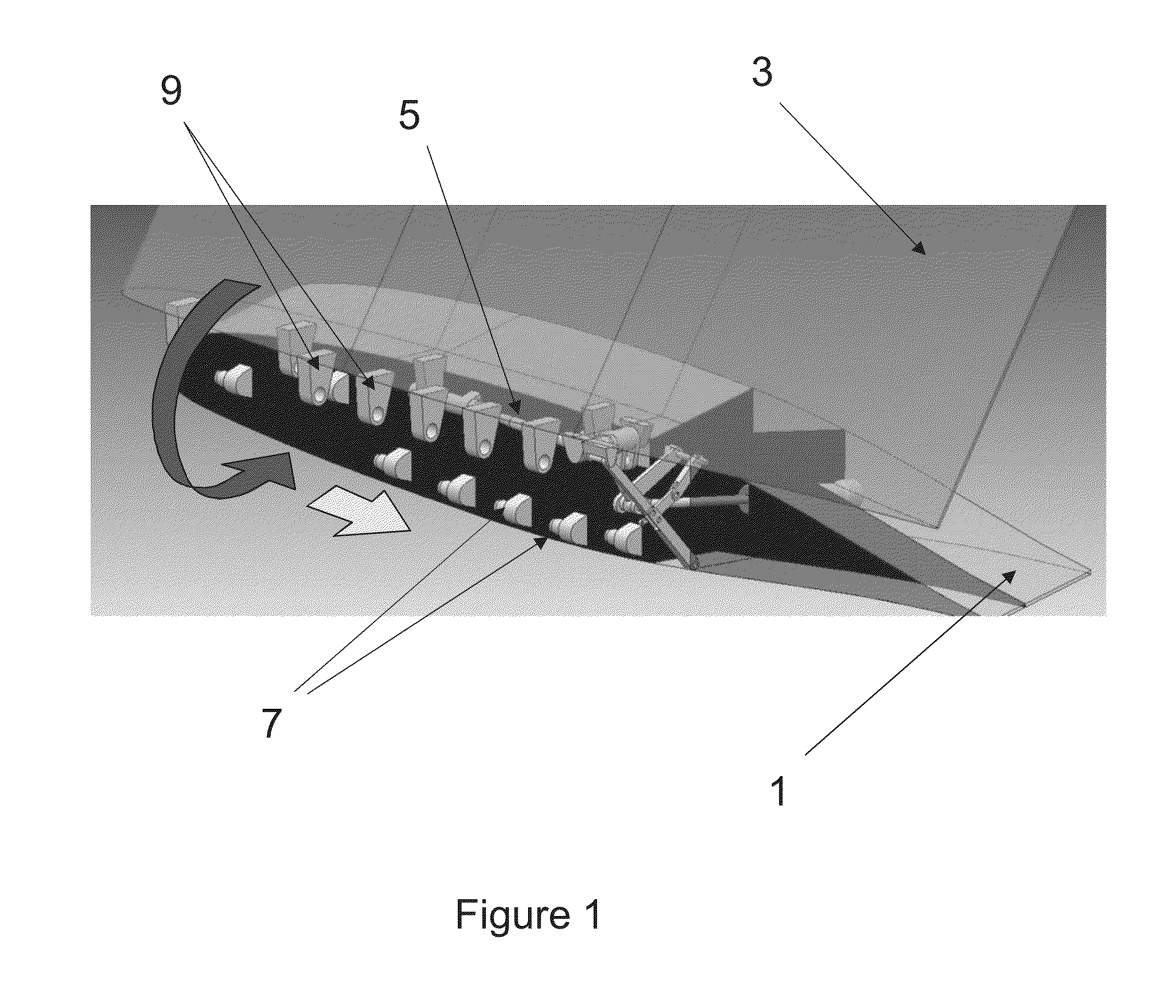
[0040]FIG. 1 shows a perspective view of a wing 1 and wing tip device 3 according to a first embodiment of the invention. The wing tip device 3 is a planar wing tip extension and is shown in a ground configuration in which the wing tip device 3 is rotated upwardly (about the hinge 5) to reduce the span of the wing 1. It will be appreciated that for the sake of clarity, the wing tip device 3 is shown in phantom and only the outer part of the wing 1 is shown.

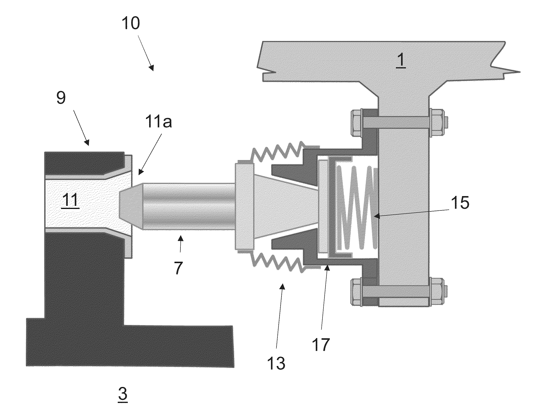
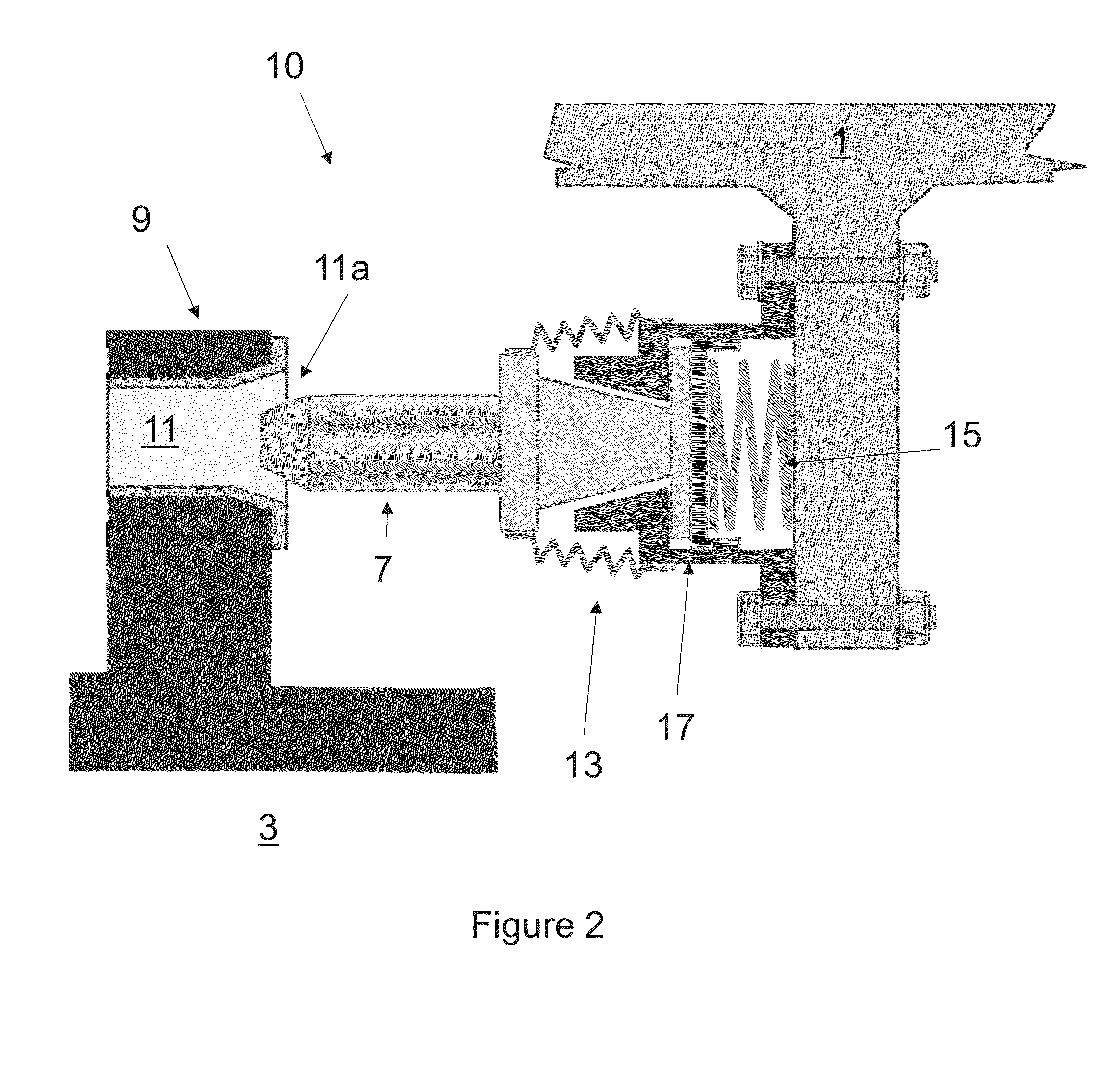
[0041]The wing tip device 3 is downwardly rotatable about the hinge 5 (in a direction shown by the large curved arrow in FIG. 1), to an intermediate configuration in which six spigots 7 associated with the wing 1 are aligned with the holes of six corresponding lugs 9 on the wing tip device 3. The wing tip device 3 is subsequently moveable in a chordwise direction (in a direction shown by the large straight arrow in FIG. 1), such that each spigot 7 engages the hole in the respective lug 9. Once the spigots 7 and lugs 9 are engaged,...


PUM


Abstract

An aircraft structure comprising a wing tip device connected to a wing by a plurality of connectors, wherein each connector comprises a spigot associated with the wing tip device or the wing, and a lug associated with the other of the wing tip device or wing. The lug has a hole for receiving the respective spigot. The spigot of each connector is moveably mounted, relative to said wing tip device or wing, about a central position, such that during movement of the connectors from a dis-engaged configuration to an engaged configuration, each spigot can move away from the central position to align itself with the hole of the respective lug.

Description

BACKGROUND OF THE INVENTION[0001]The present invention relates to connectors between first and second aircraft components (for example a wing and wing tip device), and more specifically to connectors comprising a spigot and a lug, the lug having a hole for receiving the respective spigot in a male / female connection. The present disclosure also relates to an aircraft structure comprising a first structure connected to a second structure by the plurality of connectors, and a method of connecting the two structures.[0002]There is a trend towards increasingly large passenger aircraft, for which it is desirable to have correspondingly large wing spans. However, the maximum aircraft span is effectively limited by airport operating rules which govern various clearances required when manoeuvring around the airport (such as the span and / or ground clearance required for gate entry and safe taxiway usage).[0003]In some suggested designs, aircraft are provided with wing tip devices which may be...

Claims


Application Information

Patent Timeline
IPC IPC(8): B64C3/38
CPCB64C3/38B64C3/56B64C3/26F16B5/025F16B19/02
Inventor THOMPSON, ROBERT IAN
Owner AIRBUS OPERATIONS LTD
Why Eureka
Try Eureka