Sheet material-rolling punch machine

A punching machine and plate technology, applied in the direction of punching tools, metal processing, metal processing equipment, etc., can solve the problems of low work efficiency and complicated operation, and achieve the effect of simple structure, simple and convenient operation, and reduced production time

Inactive Publication Date: 2010-06-02
无锡市威华机械有限公司
View PDF0 Cites 0 Cited by
  • Summary
  • Abstract
  • Description
  • Claims
  • Application Information

AI Technical Summary

Problems solved by technology

Low work efficiency and complex operation

Method used


Image

  • Sheet material-rolling punch machine
  • Sheet material-rolling punch machine
  • Sheet material-rolling punch machine

Examples


Embodiment Construction

[0015] Below the present invention will be further described in conjunction with the embodiment in the accompanying drawing:

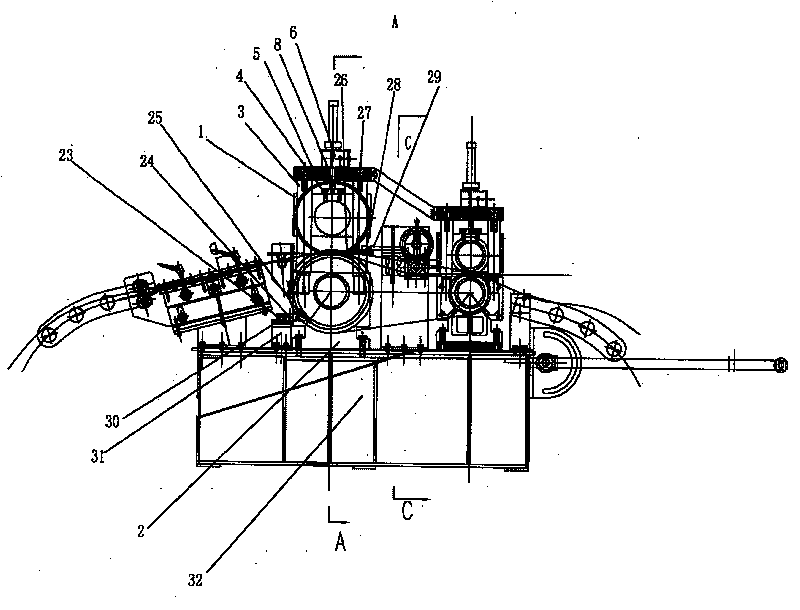
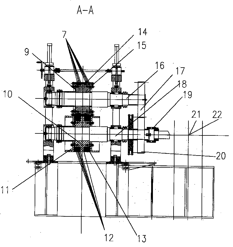
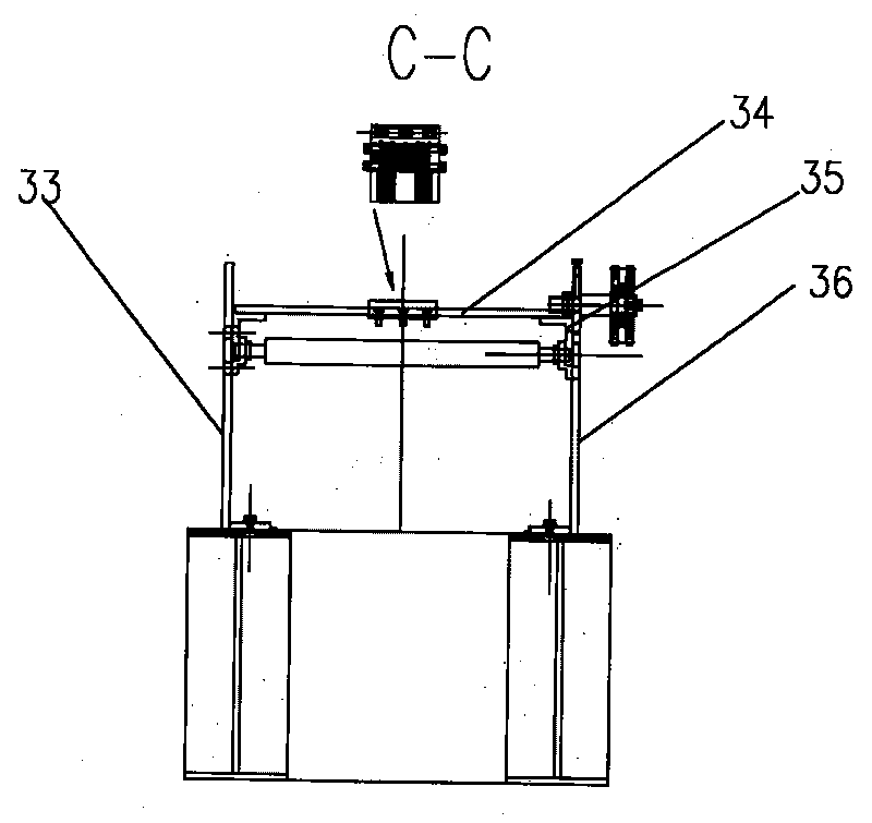
[0016] Such as Figure 1 ~ Figure 3 Shown: including upper bearing seat 1, lower bearing seat 2, guide post 3, lower hanging block 4, upper hanging block 5, elevator screw 6, upper blade 7, elevator 8, first cover plate 9, lower fixed roller 10, Idle roller 11, lower blade 12, second cover plate 13, first separator 14, upper fixed roller 15, upper shaft 16, second gear 17, lower shaft 18, coupling 19, first gear 20, motor 21 , reducer 22, lower discharge plate 23, second separator 24, lower discharge sheet 25, upper discharge sheet 26, third separator 27, upper discharge plate 28, connecting bracket 29, lower beam 30, bracket 31. Base 32, first wallboard 33, upper beam 34, fixing frame 35, second wallboard 36, etc.

[0017] In the present invention, the motor 21 is connected with the reducer 22, the reducer 22 is connected with the lower shaft 18 thr...


PUM


Abstract

The invention relates to a sheet rolling puncher, mainly comprising a motor, a speed reducer, a lower shaft, a base, an upper shaft, a lead screw lifting mechanism, a cross beam and a fixing frame. The sheet rolling puncher is characterized in that a first gear is arranged on the lower shaft; a second gear is arranged on the upper shaft; the first gear is meshed with the second gear; an upper blade and a first shim are fixed on an upper fixed roll; a first cover plate is fixed on the upper fixed roll; a lower blade, a second cover plate and a roller are fixed on a lower fixed roll; a lower stripper plate is fixed on the cross beam of a frame; a lower stripper tablet is fixed on the lower stripper plate. The sheet rolling puncher has the advantage of simple, compact and reasonable structure; continuous punching aim can be achieved; the production time can be reduced, and the working efficiency can be improved; a stamping die is provided with no fixed cavity, and the roll pass is small;the precision of the hole distance is high, and the operation is simpler and more convenient.

Description

technical field [0001] The invention relates to a plate rolling punching machine (type A), specifically for continuous punching of strip-shaped plates, and belongs to the field of mechanical manufacturing. Background technique [0002] In the existing technology, the traditional plate punching equipment mostly uses the lower die to fix, and has a fixed cavity; the upper die moves up and down to complete the plate punching requirements, and the upper die moves up and down by hydraulic cylinder or mechanical crank rotation To complete it, every time it punches a hole, the plate must move forward a little and stop before punching. The mechanical control of the moving distance is more complicated. The punching of the strip-shaped plate can be completed by repeating the operation. The work efficiency is low and the operation is more complicated. Contents of the invention [0003] The purpose of the present invention is to overcome the above disadvantages, thereby providing a ...

Claims


Application Information

Patent Timeline
Patent Type & Authority Patents(China)
IPC IPC(8): B21D28/26B21D28/34B21D28/36B21D45/08B26F1/02B26F1/14B26D7/26B26D7/18
Inventor 马建华
Owner 无锡市威华机械有限公司
Why Eureka
Try Eureka