Dye-sensitized solar cell including a porous insulation substrate and a method for producing the porous insulation substrate

a solar cell and dye-sensitive technology, applied in the field of dye-sensitive solar cells, can solve the problems of poor mechanical strength of the substrate, high demands on the porous insulation substrate, and unobtrusive environment, and achieve the effects of reducing the amount of fiber added, and enhancing the binding of non-woven fibers

Active Publication Date: 2016-07-07
EXEGER OPERATIONS AB
View PDF14 Cites 0 Cited by
  • Summary
  • Abstract
  • Description
  • Claims
  • Application Information

AI Technical Summary

Benefits of technology

The invention is a method of making a porous insulation substrate by combining the properties of woven and non-woven microfibers. By depositing a thin layer of non-woven microfibers on top of a layer of woven microfibers, the method prevents particles in inks from passing right through the woven fiber, achieving all the requirements for an ideal porous insulation substrate. The method also includes adding one or more additives to the fiberstock solution, such as a surfactant or rheology changing agent, to create a thinner and denser substrate with smaller holes.

Problems solved by technology

Unlike silicon solar cells, these cells obtain energy from sunlight using dyes which can be manufactured cheap, environmentally unobtrusive and in abundance.
There are high demands on the porous insulation substrate.
Substrates with poor mechanical strength can suffer damage during handling and processing, resulting in defect solar cells, which lower the manufacturing yield.
The substrate must have sufficient high temperature resistance and exhibit low mechanical deformation and / or small loss in mechanical stability after high temperature treatment.
This is due to the fact that non-woven glass microfibers have very poor mechanical properties, and accordingly, substrates based on non-woven glass microfibers must be produced with very high thicknesses in order to increase their mechanical stability.
A substrate with high thickness leads to a large distance between the counter electrode and the working electrode, and accordingly, to a very slow transport of ions between the counter electrode and working electrode.
However, woven fibers often have large holes between the woven yarns, which cause a large amount of particles in printed inks to pass right through the substrate in an uncontrolled way across the entire area of the woven fiber causing electrical short circuit between the counter electrode and current collector.
Thus, the holes in the fabric make it difficult to apply an ink including metallic or metal based particles on both sides of the porous insulation substrate without creating an electrical short-circuit, unless the particles are much larger than the holes.
However, having such large particles in the ink makes the conducting metal layers too thick.
Thick conducting metal layers will increase the distance between the counter electrode and the working electrode resulting in a slower ion transport between the counter electrode and the working electrode.

Method used


Image

  • Dye-sensitized solar cell including a porous insulation substrate and a method for producing the porous insulation substrate
  • Dye-sensitized solar cell including a porous insulation substrate and a method for producing the porous insulation substrate
  • Dye-sensitized solar cell including a porous insulation substrate and a method for producing the porous insulation substrate

Examples


example 1

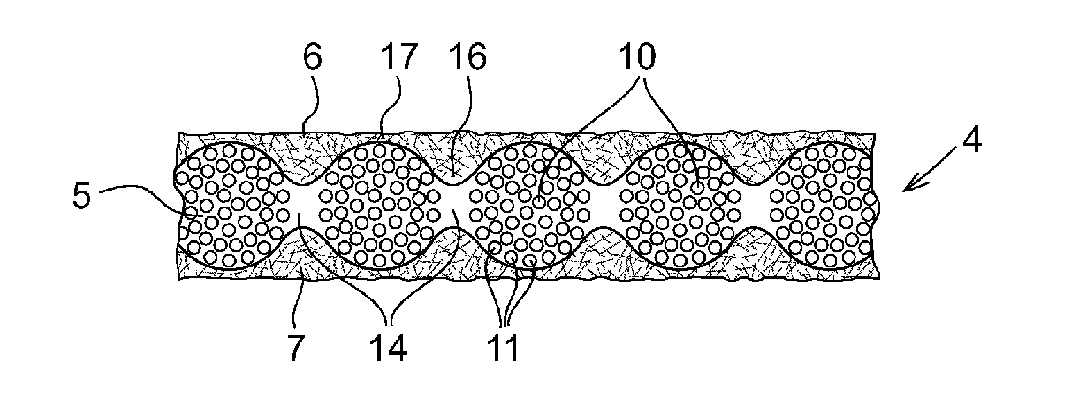
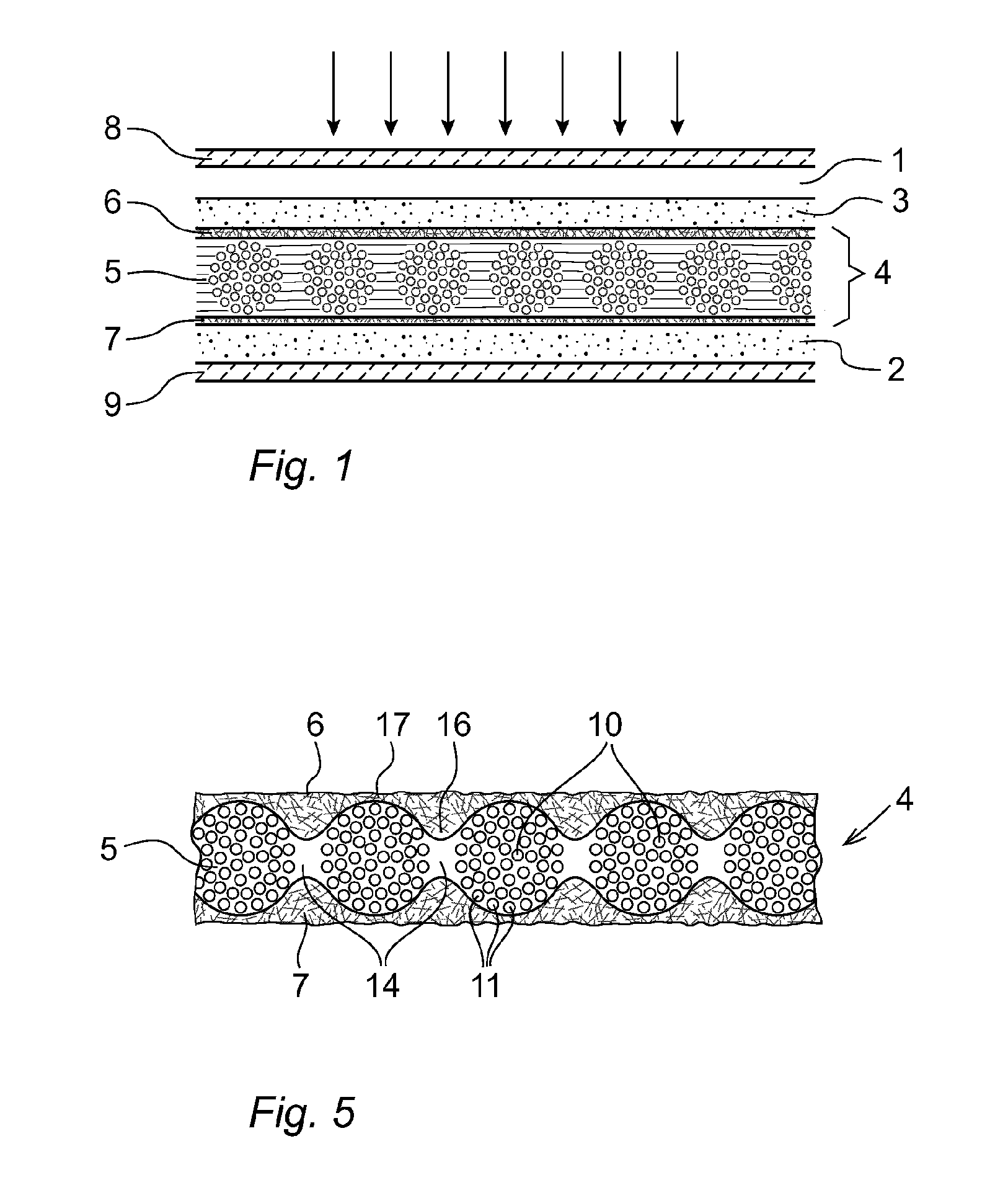
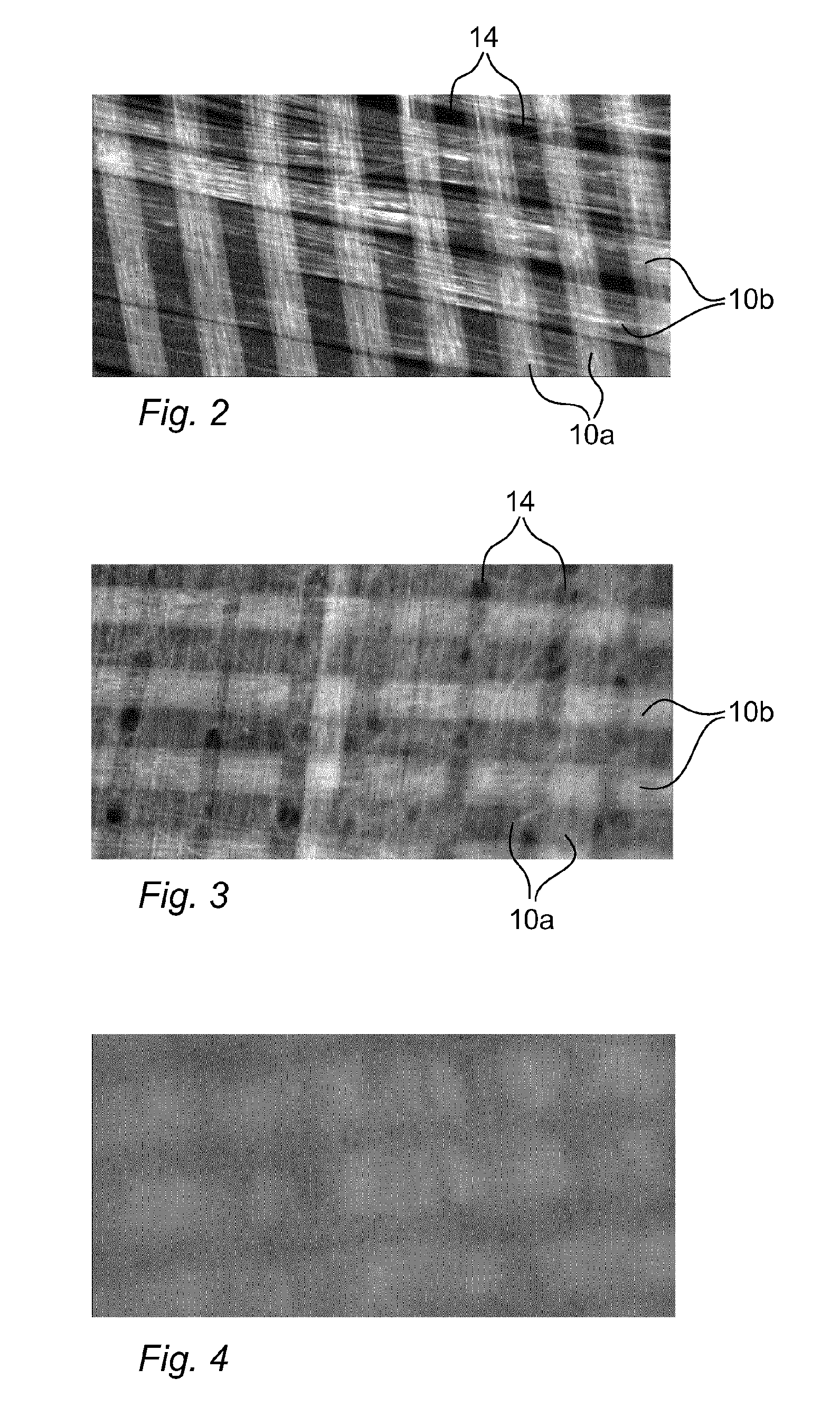
[0065]In the following an example of a method for producing the porous substrate shown in FIG. 4 will be described. A 15 μm thin glass fabric (Asahi Kasei E-materials), as shown in FIG. 2, with 50 filaments, with a filament diameter of 4 μm, was laid on top of a stainless steel wire screen (33 cm×33 cm) in a hand sheet former and a stock cylinder was put on top of the glass fabric and then closed and tightened. A glass microfiber stock solution was prepared by mixing 4000 grams of distilled water and 8 grams of glass microfibers (Johns Manville, special purpose type glass microfiber type 90, fiber diameter: 0.2 μm) and 400 grams of water based colloidal silica (a solution containing around 15 wt. % SiO2 in water) such that the final silica concentration was 1.4 wt. %. The mixing was performed using an Ultraturrax batch dispenser. The stock cylinder of the hand sheet former machine was filled with distilled water (containing 1.4 wt. % silica) up to a level of 350 mm above the surface...

example 2

[0066]A variation of Example 1 is that the microfiber stock solution is prepared by mixing 4000 grams of distilled water and 200 grams of nanocellulose dispersion (water based nanocellulose dispersion containing 2% by weight of nanocellulose) and 400 grams of water based colloidal silica (a solution containing 15 wt. % SiO2 in water). Thus, the ceramic glass microfibers in the microfiber stock solution are replaced by organic microfibers consisting of nanocellulose. Using nano-cellulose simplifies the manufacturing process in that dipping can be used instead of using a paper manufacturing process.

example 3

[0067]Another variation of example 1 is that the microfiber stock solution is prepared by mixing 4000 grams of distilled water and 2 grams of glass microfibers (Johns Manville, special purpose type glass microfiber type 90, fiber diameter: 0.2 μm) and 200 grams of nanocellulose dispersion (water based nanocellulose dispersion containing 2% by weight of nanocellulose) and 400 grams of water based colloidal silica (a solution containing 15 wt. % SiO2 in water). Thus, both organic microfibers consisting of nanocellulose and ceramic microfibers consisting of glass are used in the microfiber stock solution. After the porous insulation substrate has been dried, ink with conductive particles is deposited on at least one side of the substrate on top of the layer of non-woven microfibers, to form a porous conducting layer on the porous insulation substrate. If a monolithic DCS module is to be manufactured, the ink is deposited on both sides of the substrate on top the layers of non-woven mic...


PUM

PropertyMeasurementUnit
temperaturesaaaaaaaaaa

Abstract

The present invention relates to a dye-sensitized solar cell including a working electrode (1), a first conducting layer (3) for extracting photo-generated electrons from the working electrode, a porous insulation substrate (4) made of a microfibers, wherein the first conducting layer is a porous conducting layer formed on one side of the porous insulation substrate, a counter electrode including a second conducting layer (2) arranged on the opposite side of the porous substrate, and electrolyte for transferring electrons from the counter electrode to the working electrode. The porous insulation substrate comprises a layer (5) of woven microfibers and a layer (6) of non-woven microfibers disposed on the layer of woven microfibers. The present invention also relates to a method for producing a dye-sensitized solar cell.

Description

FIELD OF THE INVENTION[0001]The present invention relates to a dye-sensitized solar cell including a porous insulation substrate made of microfibers, having a first conducting layer formed on one side of the porous insulation substrate, and a second conducting layer arranged on the opposite side of the porous substrate. The present invention further relates to a porous insulation substrate for a dye-sensitized solar cell. The present invention also relates to a method for producing the porous insulation substrate and the conducting layers.PRIOR ART[0002]Dye-sensitized solar cells (DSC) have been under development for the last 20 years and work on similar principles as photosynthesis. Unlike silicon solar cells, these cells obtain energy from sunlight using dyes which can be manufactured cheap, environmentally unobtrusive and in abundance.[0003]A conventional sandwich type dye-sensitized solar cell has a few μm thick porous TiO2 electrode layer deposited onto a transparent conducting...

Claims


Application Information

Patent Timeline
Patent Type & Authority Applications(United States)
IPC IPC(8): H01G9/20H01G9/00B05D7/00
CPCH01G9/20H01G9/0032B05D7/544H01G9/2068H01G9/2081H01G9/2031H01G9/2059B32B5/26H01G9/2095B32B5/022B32B5/024B32B2457/12Y02E10/542Y02E10/549Y02P70/50H01L31/04H01L31/00H01L31/022425B32B2262/10H10K71/611
Inventor LINDSTROM, HENRIKFILI, GIOVANNI
Owner EXEGER OPERATIONS AB
Why Eureka
Try Eureka