Raw material gas supply apparatus and film forming apparatus

Active Publication Date: 2016-09-22
TOKYO ELECTRON LTD
View PDF3 Cites 179 Cited by
  • Summary
  • Abstract
  • Description
  • Claims
  • Application Information

AI Technical Summary

Benefits of technology

[0009]In view of the above, the disclosure provides a technique that can stabilize a sublimation flow rate of a raw material

Problems solved by technology

Such a technique is disadvantageous in that when the remaining amount of the raw material is decreased as the sublimation proceeds, a sublimation flow rate of the raw material is decreased, and when the remaining amount of the raw material is excessively small, the amount of the raw material supplied to the processing chamber becomes unstable.
The present inventors have studied a technique for stabilizing the s

Method used


Image

  • Raw material gas supply apparatus and film forming apparatus
  • Raw material gas supply apparatus and film forming apparatus
  • Raw material gas supply apparatus and film forming apparatus

Examples


first embodiment

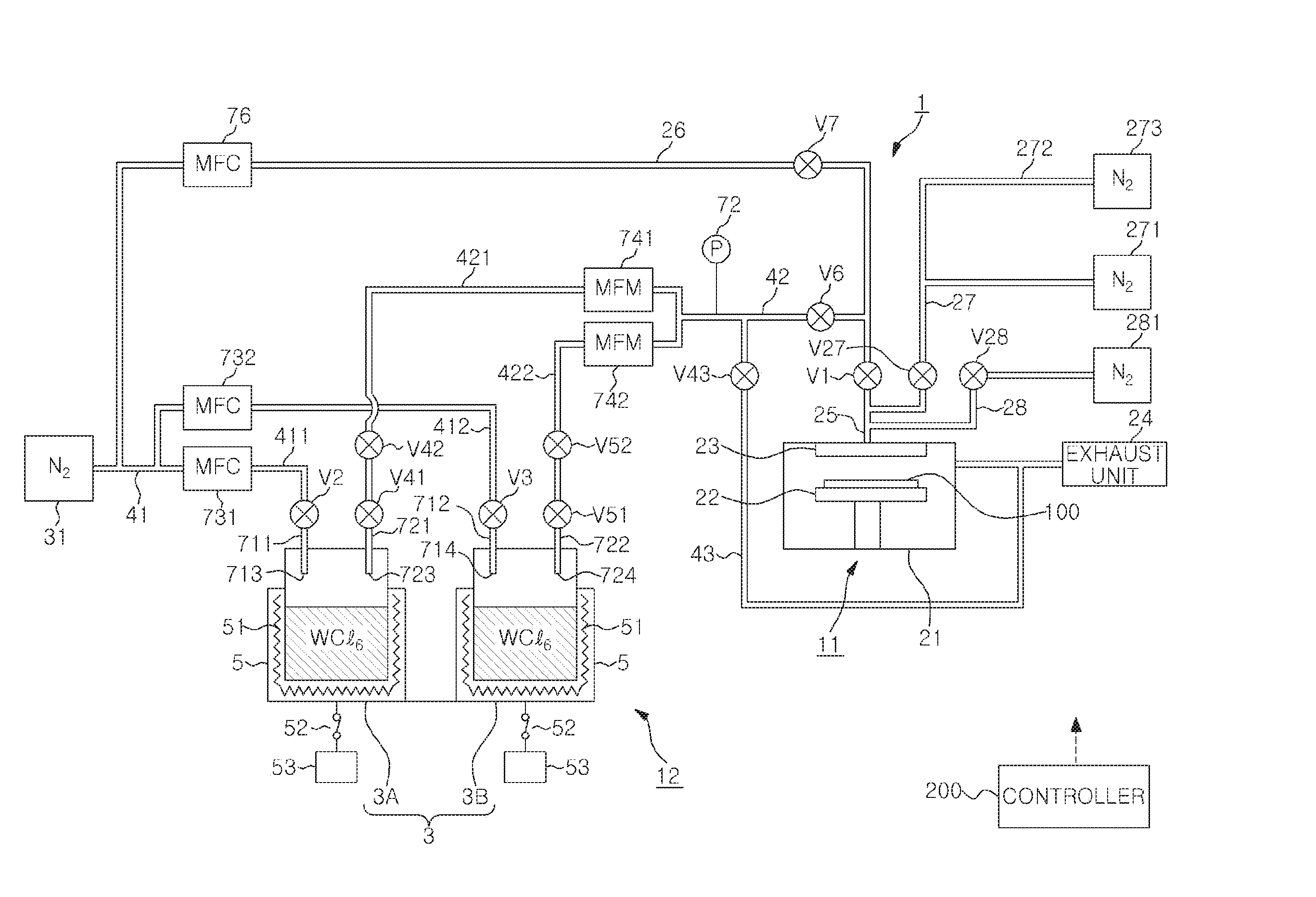
[0019]Hereinafter, a configuration example of a first embodiment of a film forming apparatus including a raw material gas supply apparatus will be described with reference to FIG. 1. A film forming apparatus 1 includes a film forming unit 11 serving as a consumption area where a film forming process using, e.g., an ALD method, is performed on a wafer 100 as a substrate, and a raw material gas supply apparatus 12 for supplying a raw material gas to the film forming unit 11. The film forming unit 11 includes a mounting table 22 having a heater (not shown), and a gas inlet 23 for introducing a raw material gas and the like into a processing chamber 21, e.g., a vacuum container. The mounting table 22 is configured to horizontally support the wafer W in the processing chamber 21. The processing chamber 21 is evacuated by a vacuum exhaust unit 24 including a vacuum pump or the like. By introducing the raw material gas into the processing chamber 2 from a raw material gas supply apparatus ...

second embodiment

[0068]Next, a film forming apparatus according to a second embodiment will be described with reference to FIG. 4. This film forming apparatus is different from the film forming apparatus shown in FIG. 1 in that a buffer chamber is connected to the raw material container.

[0069]As shown in FIG. 4, a buffer chamber 84 is connected to, e.g., a ceiling portion of each of the first and the second raw material container 3A and 3B through a raw material outlet line 841 through which a sublimated raw material of the solid raw material is discharged. The first and the second carrier gas inlet line 411 and 412 and the first and the second raw material gas line 421 and 422 are connected to the buffer cambers 84 of the first and the second raw material container 3A and 3B through the carrier gas nozzles 711 and 712 and the extracting nozzles 721 and 722, respectively.

[0070]Accordingly, a partitioning unit for partitioning gas flow discharged from the outlet ports 713 and 714 and the area near th...

third embodiment

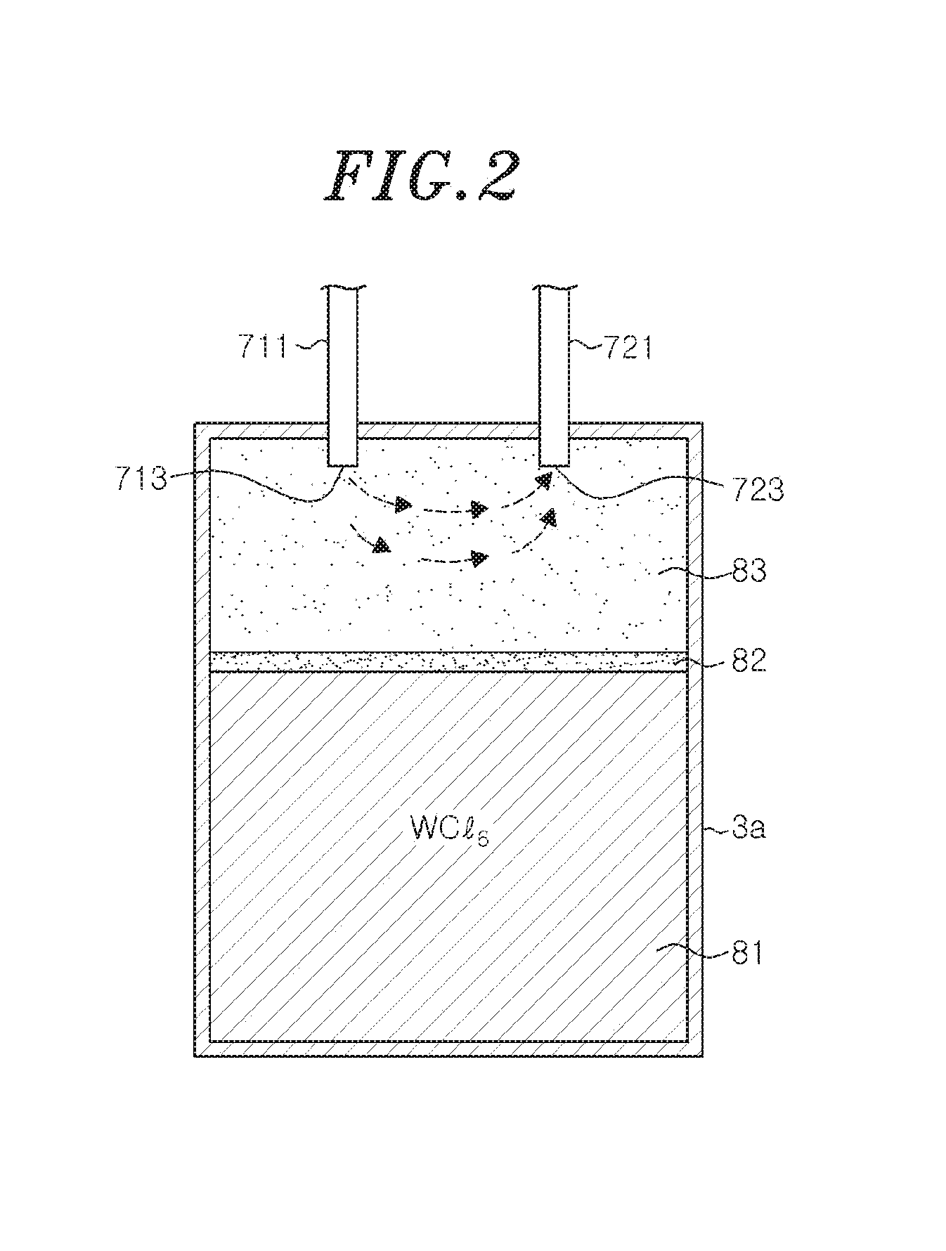
[0074]Next, a film forming apparatus according to a third embodiment will be described with reference to FIG. 5. This film forming apparatus is different from the film forming apparatus shown in FIG. 1 in that a partitioning unit for partitioning the gas flow discharged from the outlet ports of the carrier gas nozzles and the surface of the solid raw material is provided between the outlet ports and the solid raw material in the raw material container.

[0075]FIG. 5 shows the state in which the solid raw material is filled in the first and the second raw material container 3A and 3B. For example, a partitioning unit 85 is provided to partition the diffusion layer 82 and the vapor layer 83 when the raw material container 3A is heated to a set temperature in a state where the solid raw material 81 is filled. Therefore, the partitioning unit 85 includes: a plate-shaped member 851 provided along the surface of the solid raw material in order to divide the raw material container 3A into an...


PUM

PropertyMeasurementUnit
Fractionaaaaaaaaaa
Areaaaaaaaaaaa

Abstract

A raw material gas supply apparatus includes a raw material container, a carrier gas inlet line and a raw material gas line. The raw material container is configured to accommodate the solid raw material. The carrier gas inlet line is configured to discharge the carrier gas to the raw material gas originated from the solid raw material. The raw material gas is transferred to the consumption area together with the carrier gas through the raw material gas line. A flow rate of the carrier gas is set such that a variation rate of a gas flow rate of the raw material gas flowing in the raw material gas line obtained by subtracting a gas flow rate in the carrier gas inlet line from a gas flow rate in the raw material gas line becomes 10% or less.

Description

CROSS-REFERENCE TO RELATED APPLICATIONS[0001]This application claims priority to Japanese Patent Application No. 2015-053402 filed on Mar. 17, 2015, the entire contents of which are incorporated herein by reference.FIELD OF THE INVENTION[0002]The disclosure relates to a raw material gas supply apparatus for supplying a raw material gas originated from a solid raw material to a consumption area together with a carrier gas, and a film forming apparatus using the same.BACKGROUND OF THE INVENTION[0003]A CVD (Chemical Vapor Deposition) method or an ALD (Atomic Layer Deposition) method is known as a method for forming a film on a substrate such as a semiconductor wafer (hereinafter, referred to as “wafer”) or the like. The operations of such a method are performed by accommodating the wafer in a processing chamber in which a vacuum atmosphere is formed and supplying a raw material gas into the processing chamber.[0004]In the case of using a solid raw material, the raw material is sublimat...

Claims


Application Information

Patent Timeline
IPC IPC(8): C23C16/448C23C16/52C23C16/455
CPCC23C16/4485C23C16/52C23C16/45561C23C16/14C23C16/4481
Inventor KOMORI, EIICHIYAGI, HIRONORI
Owner TOKYO ELECTRON LTD
Why Eureka
Try Eureka