
Well casing stop collar

a technology of stop collars and well casings, applied in the direction of drilling casings, drilling pipes, drilling rods, etc., can solve the problems of reducing the ability of the stop collar to cock, the self-tighten the cocking of the stop collar, so as to increase the longitudinal force and increase the braking force

Inactive Publication Date: 2016-09-22
PORTABLE COMPOSITE STRUCTURES
View PDF0 Cites 2 Cited by
  • Summary
  • Abstract
  • Description
  • Claims
  • Application Information

AI Technical Summary

Benefits of technology

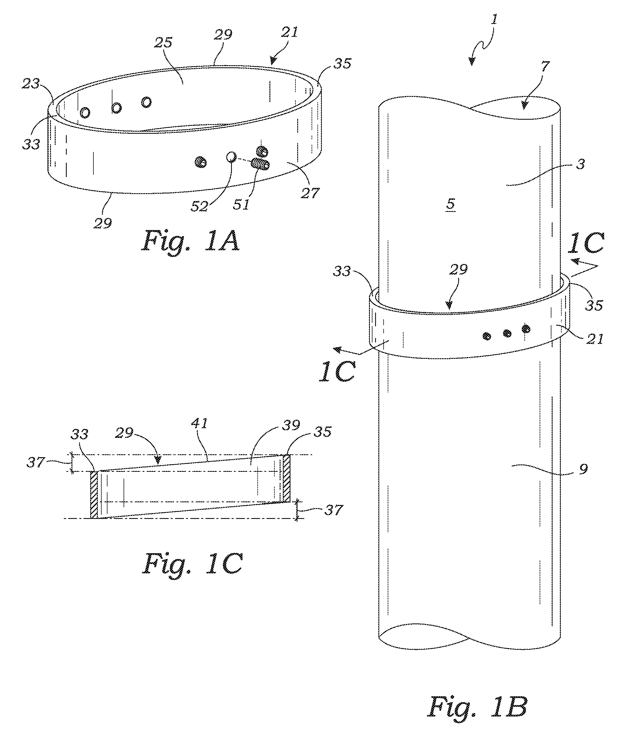
The stop collar in the patent text is designed to create a braking force when exposed to a longitudinal force from an object around a pipe or shaft. This occurs because the object will make contact with the stop collar and cause it to rotate out of concentric alignment with the pipe. This in turn results in increased braking force as the collar's proximal engagement point digs into the pipe.

Problems solved by technology

Advantageously, this results in the stop collar being self-tightening in the event that the stop collar engages an object (such as a tool, sensor or obstruction) as the stop collar is slid down a bore such as a well hole.
This force on the distal engagement point results in the stop collar cocking due to the inherent discrepancy between the outer diameter of the casing and the inner diameter of stop collar until the stop collar's proximal engagement point engages the pipe.
Conversely, a decrease in the annular space between the stop collar and the pipe decreases the capability of the stop collar to cock prior the stop collar's proximal engagement point engaging the pipe sidewall.

Method used


Image

  • Well casing stop collar
  • Well casing stop collar
  • Well casing stop collar

Examples


Embodiment Construction

[0038]While the present invention is susceptible of embodiment in various forms, as shown in the drawings, hereinafter will be described the presently preferred embodiments of the invention with the understanding that the present disclosure is to be considered as an exemplification of the invention, and it is not intended to limit the invention to the specific embodiments illustrated.

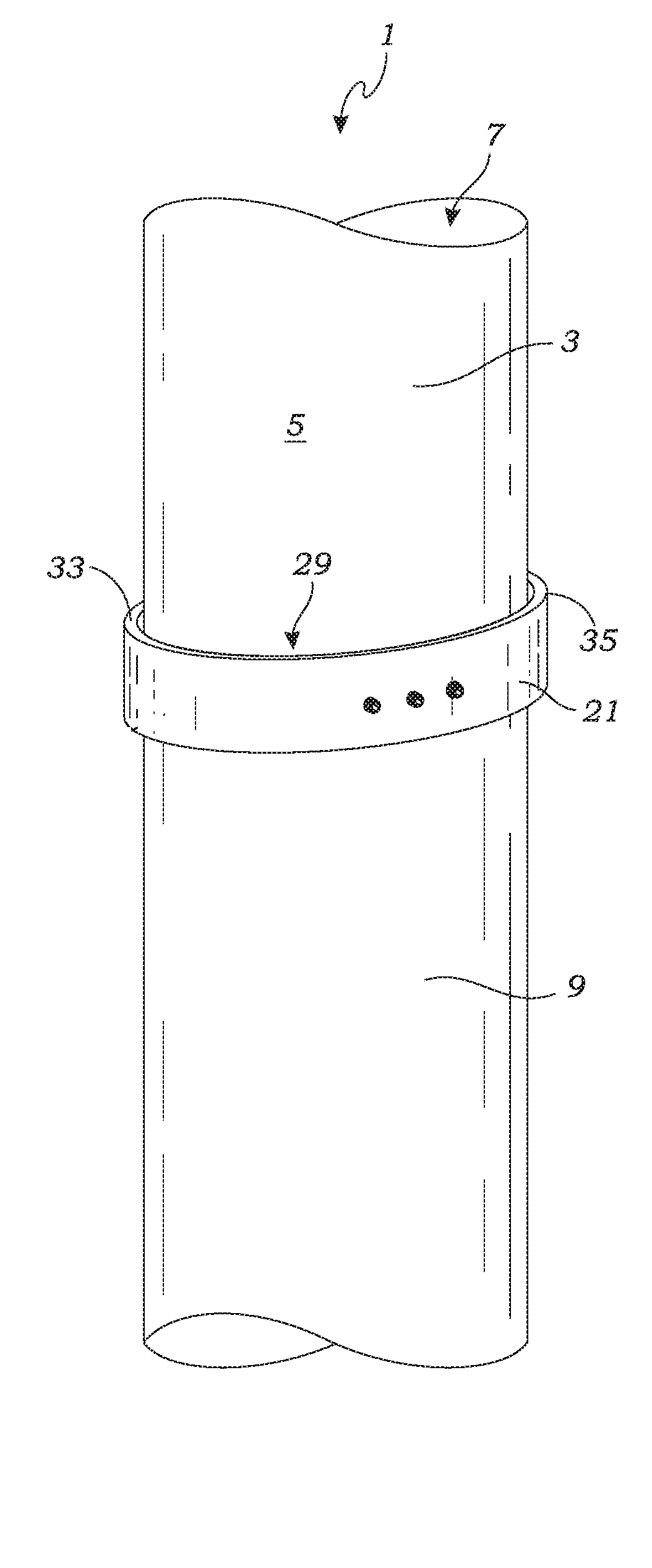
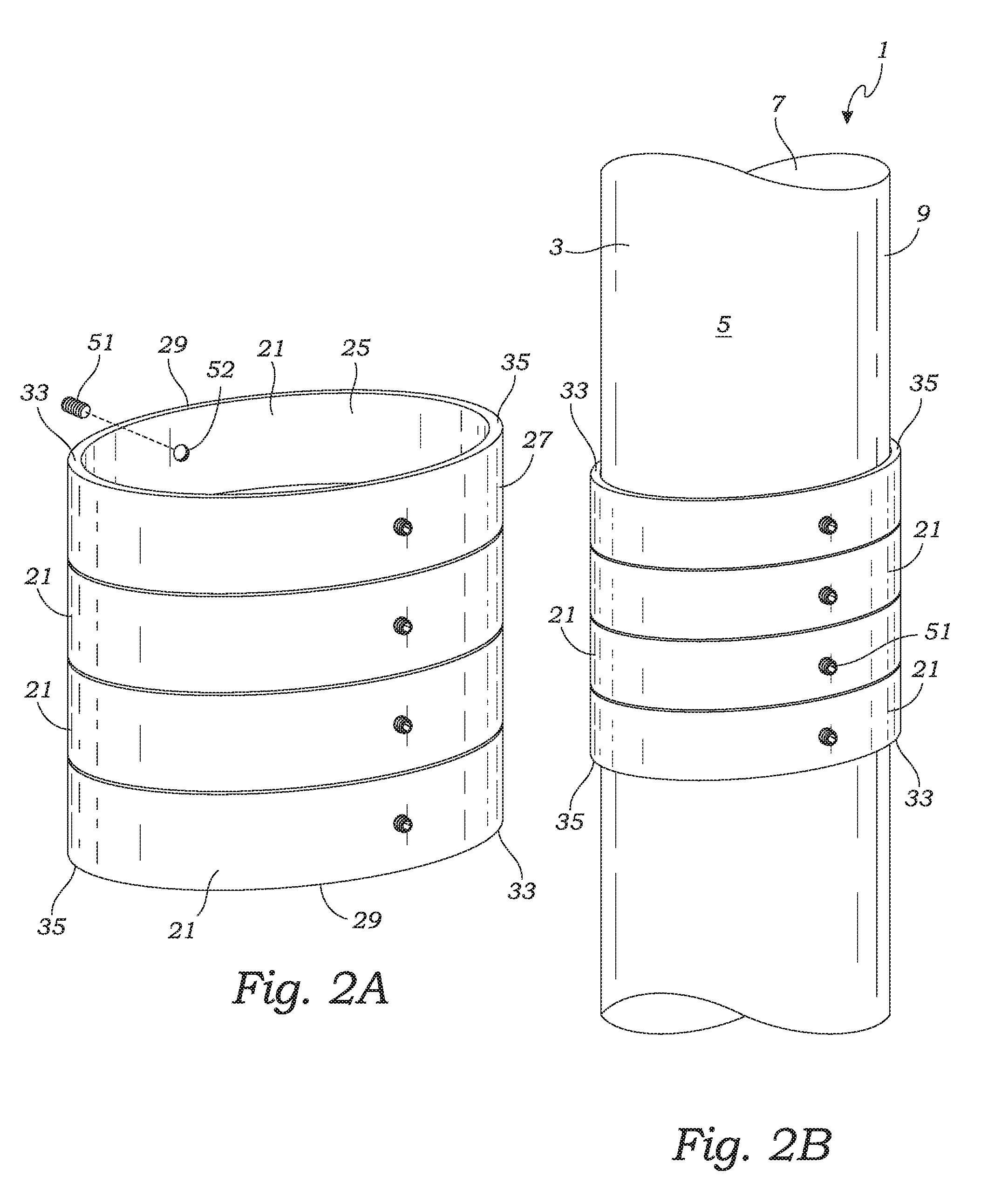
[0039]With reference to FIGS. 1A-8B, the pipe and collar assembly 1 incorporates a pipe 3 and a stop collar 21. The pipe 3 has a traditional elongate annular construction including a circular sidewall 5 forming a central conduit 7 which defines the pipe's longitudinal axis. Meanwhile, the stop collar 21 includes a ring-shaped body 23 having a center hole. The stop collar's ring-shaped body has an exterior surface 9, and an interior surface 25 with a diameter the same or slightly larger than the pipe's exterior diameter. In addition, the stop collar 21 has two opposed ends referred to herein as a leading...


PUM


Abstract

A stop collar for pipes or shafts is provided for restricting objects from sliding lengthwise along the length of a pipe or shaft. The stop collar is ring-shaped and includes a leading edge which is angled from perpendicular to the pipe's longitudinal axis. The angled leading edge provides the leading edge with a proximal engagement point and a distal engagement point. Longitudinal force on the distal engagement point, by an object such as a tool or sensor, causes the stop collar to cock relative to the pipe or shaft. This cocking of the stop collar effects a braking function to prevent the stop collar from sliding longitudinally along the pipe.

Description

RELATED APPLICATIONS[0001]The present application is a continuation-in-part of co-pending U.S. Provisional Patent Application Ser. No. 62 / 134,115 filed on Mar. 17, 2015. The contents of the aforementioned application are incorporated by reference herein.BACKGROUND OF THE INVENTION[0002]The invention relates to devices which grip tubular members, such as a drill pipe. More particularly, the invention relates to locking collars for positioning and affixing objects to a drill pipe.[0003]In the field of oil well drilling, various tools and appliances, such as centralizers, scratchers, solidifiers, baskets, and the like, have been developed for centering the casing within the wellbore or for cleaning or otherwise scraping the walls of the bore to facilitate the placing of the cement column around the casing and to assure a satisfactory bonding of the column to the wall of the well. In addition, various tools and sensors must be located downhole in a wellbore which are typically mounted u...

Claims


Application Information

Patent Timeline
Patent Type & Authority Applications(United States)
IPC IPC(8): E21B17/00
CPCE21B17/006E21B17/1078
Inventor JEWETT, SCOTT E.
Owner PORTABLE COMPOSITE STRUCTURES
Learn More