Installation structure of automobile radiator system

A technology for automobile radiator and system installation, which is applied to the arrangement of cooling combination of power units, power units, vehicle components, etc. Cost, reduce stress, and improve the effect of longitudinal force capacity

Inactive Publication Date: 2016-02-10
力帆科技(集团)股份有限公司
View PDF5 Cites 1 Cited by
  • Summary
  • Abstract
  • Description
  • Claims
  • Application Information

AI Technical Summary

Problems solved by technology

If the mounting pin hole positions of the upper and lower beams of the water tank are changed, although the radiator core will not be affected, this will increase the manufacturing cost and increase the types of parts, which is not conducive to the management of parts

Method used


Image

  • Installation structure of automobile radiator system
  • Installation structure of automobile radiator system
  • Installation structure of automobile radiator system

Examples


Embodiment Construction

[0023] The present invention will be further described below in conjunction with drawings and embodiments.

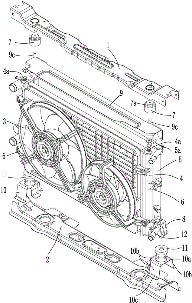
[0024] Such as figure 1 The installation structure of the automobile radiator system shown is mainly composed of the radiator system, the upper beam of the water tank 1, the lower beam of the water tank 2, two rubber suspensions 7, the upper radiator mounting plate 9, the lower radiator mounting bracket 10, two shockproof Rubber pad 11 forms. The radiator system mainly consists of a fan 3 , a first radiator 4 and a second radiator 5 . The upper beam 1 of the water tank is located above the radiator system, and the lower beam 2 of the water tank is located below the radiator system.

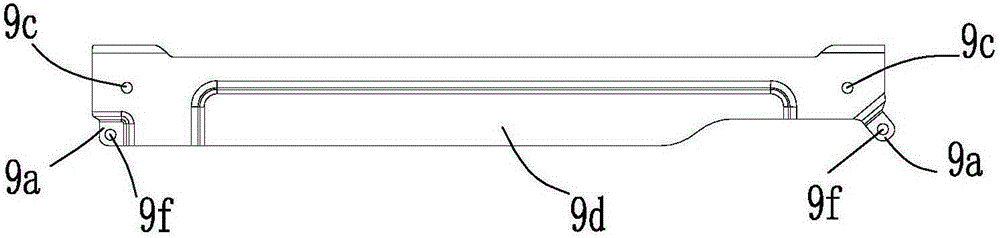
[0025] combine figure 1 , image 3 , Figure 4 As shown, between the upper beam 1 of the water tank and the radiator system, there is an upper mounting plate 9 on the radiator. The upper mounting plate 9 on the radiator is equal in length and width to the radiator system, and is a stam...


PUM


Abstract

The invention discloses an automobile radiator system mounting structure. The automobile radiator system mounting structure comprises a radiator system, a water tank upper cross beam (1) and a water tank lower cross beam (2). The radiator system comprises a fan (3), a first radiator (4) and a second radiator (5) which are sequentially mounted together in a superposition mode front from front to back; a radiator upper mounting plate (9) is mounted between the water tank upper cross beam and the radiator system, and radiator lower mounting supports (10) are mounted between the left end of the water tank lower cross beam and the radiator system as well as the right end of the water tank lower cross beam and the radiator system; the radiator upper mounting plate and the first radiator are of a longitudinal fixing mode, and the radiator upper mounting plate and the second radiator are of a horizontal fixing mode. The automobile radiator system mounting structure does not change the mounting pin holes of the water tank upper cross beam and the water tank lower cross beam, and meanwhile, the radiator system are provided with two radiators, so that not only is the radiation capacity of the radiators can be improved significantly, but also the insufficient stress capacity of the radiator system during the driving process can be effectively avoided.

Description

technical field [0001] The invention relates to an installation structure of auto parts, in particular to an installation structure of a radiator system for cooling an engine. Background technique [0002] The automobile radiator includes a water inlet chamber and a water outlet chamber, and a core body is arranged between the water inlet chamber and the water outlet chamber, and the core body is composed of a plurality of heat dissipation pipes arranged side by side. The radiator is a heat exchanger, which can be divided into longitudinal flow type and cross flow type according to the direction of coolant flow in the radiator. The water inlet and outlet chambers of the cross-flow radiator are arranged on the left and right sides, and the coolant flows through the radiator core horizontally; the inlet and outlet chambers of the longitudinal flow radiator are arranged on the upper and lower sides, and the coolant flows through the radiator device core. For longitudinal flow...

Claims


Application Information

Patent Timeline
Patent Type & Authority Patents(China)
IPC IPC(8): B60K11/04
Inventor 杨柳荫王弟伟殷军
Owner 力帆科技(集团)股份有限公司
Why Eureka
Try Eureka