Reinforcing strip for a wind turbine blade

a technology of wind turbine blades and reinforcement strips, which is applied in the direction of motors, applications, domestic articles, etc., can solve the problems of not being able to propagate through the regions of cured resin in the slots, and achieve the effect of reducing time and cost, and reducing the number of manufacturing steps

Inactive Publication Date: 2016-09-22
VESTAS WIND SYST AS
View PDF2 Cites 18 Cited by
  • Summary
  • Abstract
  • Description
  • Claims
  • Application Information

AI Technical Summary

Benefits of technology

[0034]The method may comprise visually inspecting a length of the or each slot of the strip, and, if the length of the slot is below a threshold length, replacing the strip with a different strip, or machining the tapered end of the strip. This is a particular advantage of the present invention: the slots allow for easy visual inspection of the quality of the tapered end portion of the strip. This is in contrast to conventional strips, for which checking the quality of the tapered ends involves making a number of measurements and is relatively time consuming.
[0035]The invention also extends to an elongate reinforcing structure for a wind turbine blade made according to the method described above.
[0036]From another aspect, the invention resides in a method of making a strip for an elongate reinforcing structure of a wind turbine blade, the method comprising: a) providing an elongate strip of fibre-reinforced polymeric material, the strip having upper and lower substantially flat surfaces and extending longitudinally between first and second transverse edges; b) shaping an end region of the strip to form a tapered end region of the strip that tapers in thickness towards a transverse edge of the strip; and c) forming at least one slot in the strip that extends longitudinally from the transverse edge of the strip into the tapered end region.
[0037]Steps (b) and (c) may occur simultaneously, such that the tapered end region and the or each slot may be formed at the same time. This reduces the number of manufacturing steps, and hence reduces the time and cost required for the manufacturing process.
[0038]Step (a) may comprise forming the strip by a pultrusion process wherein reinforcing fibres are drawn through a pultrusion die.
[0039]The method may comprise forming one or more longitudinally-extending grooves in the upper and / or lower surface of the strip, the grooves extending along at least part of the tapered end region of the strip. In embodiments where the strip is formed by a pultrusion process, the pultrusion die may comprise features arranged to form the grooves in the strip as part of the pultrusion process. In this way, the grooves can be provided on the strip as the strip is pultruded, thereby removing the need for a separate groove-forming step.

Problems solved by technology

These regions of cured resin act as crack-stoppers: air pockets trapped between strips and beneath the tapered end region of a strip, which can act as cracks that propagate to delaminate the strips, will not be able to propagate through the regions of cured resin in the slots.

Method used


Image

  • Reinforcing strip for a wind turbine blade
  • Reinforcing strip for a wind turbine blade
  • Reinforcing strip for a wind turbine blade

Examples


second embodiment

[0091]A strip 232 according to the invention, in which grooves 254 are provided in the upper surface 236 of the strip 232, rather than the lower major 234 surface of the strip 232, will now be described with reference to FIGS. 13 to 18.

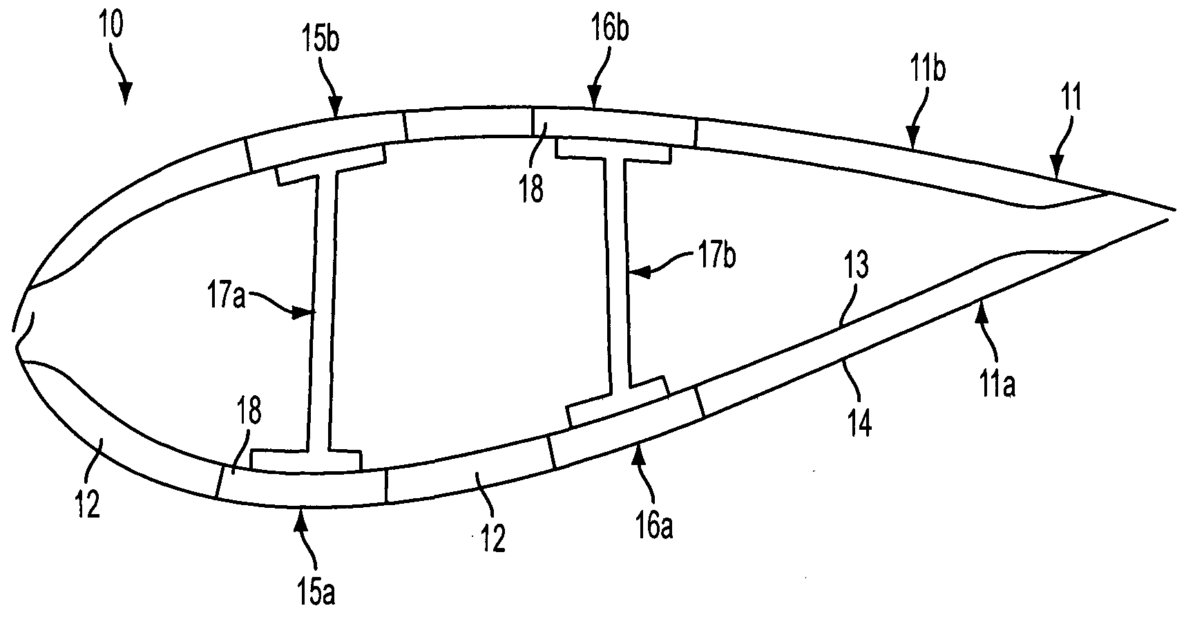
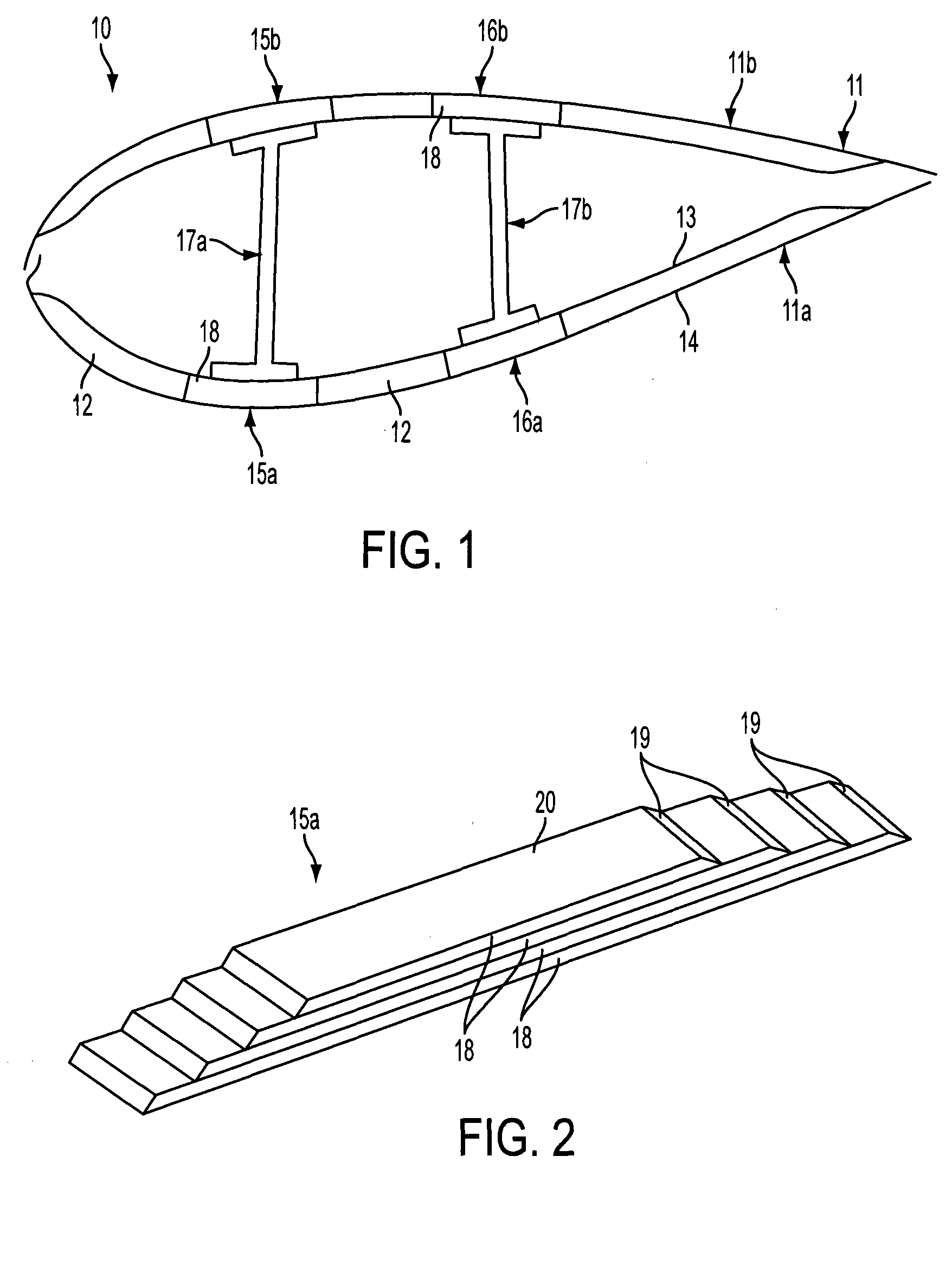
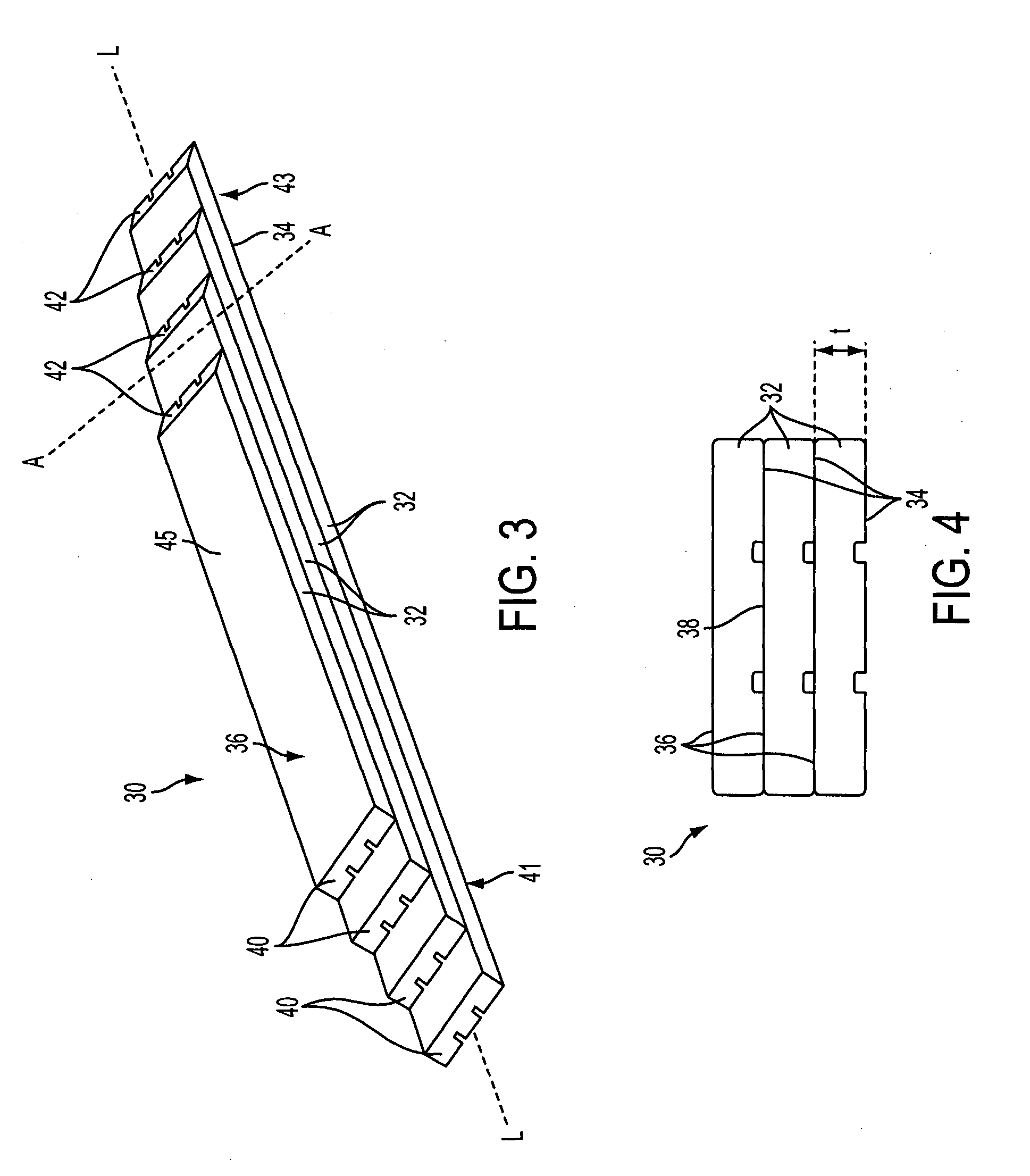
[0092]FIGS. 13 and 14 illustrate a spar cap 230 incorporating a plurality of strips according to the second embodiment of the invention. The spar cap 230 is of substantially the same form as the spar cap 30 of FIG. 3, being comprised of a plurality of stacked strips 232, and so will not be described in further detail to avoid repetition.

[0093]Each strip 232 is of generally the same form as the strip 32 illustrated in FIG. 5. In particular, the configuration of the upper and lower surfaces 234, 236, the tapered end portions 244 of the upper surface 234, and the transverse edges 246 are substantially the same, and will not be described again in detail to avoid repetition.

[0094]As shown in FIG. 15, the strips 232 according to the second embodiment compri...

first embodiment

[0096]As mentioned with regard to the first embodiment, the shape of the grooves 254 controls the shape of the corresponding slots 250. The slots 250 emerge in the lower surface 234 when the thickness of the strip 232 becomes less than the depth of the groove 254. Referring now to FIG. 18, due to the tapered walls 257 of the grooves 254, the width of the slots 250 varies. At the edge 246 of the strip 232, the slot 250 is at its widest and has a width equal to the width w′ at the mouth of the groove 254. The width of the slot 250 decreases as the slot 50 extends into the tapered end surface 244, until the slot terminates with a width that is equal to the width w″ of the base 255 of the groove 254. In the way, the slots 250 are generally ‘V’-shaped.

[0097]The strips 232 are integrated into the spar cap 230 using the resin-infusion process that has already been described above with reference to the first embodiment and so will not be described here to avoid repetition.

[0098]When a strip...


PUM

PropertyMeasurementUnit
thicknessaaaaaaaaaa
distanceaaaaaaaaaa
lengthaaaaaaaaaa

Abstract

A strip of fibre-reinforced polymeric material for a longitudinal reinforcing structure of a wind turbine blade, the strip having substantially flat upper and lower surfaces and extending longitudinally between first and second transverse edges, wherein an end region of the strip tapers in thickness towards the first transverse edge, and wherein one or more slots are defined in the tapered end region, the or each slot extending longitudinally from the first transverse edge of the strip into the tapered end region.

Description

FIELD OF THE INVENTION[0001]The present invention relates to wind turbine components that include a stack of load-bearing structural elements, to methods of making such components and to structural elements for use in such components. In particular embodiments of the invention, the components are spar caps comprising a stack of reinforcing strips that are integrated within the shell of a wind turbine blade.BACKGROUND TO THE INVENTION[0002]FIG. 1 illustrates in cross-section a wind turbine rotor blade 10. The blade 10 has an outer shell 11 that is fabricated from two half shells: a windward shell 11a and a leeward shell 11b. The shells 11a, 11b are moulded from glass-fibre reinforced plastic (GRP). Parts of the outer shell 11 are of sandwich panel construction and comprise a core 12 of lightweight foam (e.g. polyurethane) sandwiched between inner and outer GRP layers or ‘skins’13, 14.[0003]The blade 10 comprises a first pair of spar caps 15a, 15b and a second pair of spar caps 16a, 1...

Claims


Application Information

Patent Timeline
Patent Type & Authority Applications(United States)
IPC IPC(8): F03D1/06B32B5/26B32B3/26B32B3/30F03D1/00B32B3/02
CPCF03D1/0675F03D1/001B32B3/02B32B3/263B32B3/30B32B2603/00F05B2280/4003F05B2280/6003F05B2280/6015F05B2230/24B32B5/26F05B2230/10F05B2230/41F05B2280/2006B29C70/521B29D99/0028B32B2260/021B32B2260/046B32B2262/106F03D13/10B29C70/526B29C70/545B29L2031/003B29C67/0044B29C2793/009B29L2031/085Y02E10/72Y02P70/50B29C70/302
Inventor SMITH, JONATHANGILL, ADRIANHANCOCK, MARK
Owner VESTAS WIND SYST AS
Why Eureka
Try Eureka