Gas purge apparatus, load port apparatus, and gas purge method

a gas purge and load port technology, applied in the direction of electric devices, conveyor parts, transportation and packaging, etc., can solve the problems of purge gas leaked, wafers placed on a shelf inside the container may be damaged, and the handling performance of wafers is deteriorated, so as to achieve the effect of introducing purge gas into the entire container

Active Publication Date: 2016-09-22
TDK CORPARATION
View PDF22 Cites 17 Cited by
  • Summary
  • Abstract
  • Description
  • Claims
  • Application Information

AI Technical Summary

Benefits of technology

[0018]In the gas purge apparatus according to the present invention, when the purge nozzles are connected to the purge ports, the first purge nozzle whose distance to the regulating position is short is made contact with the purge port before the second purge nozzle whose distance to the regulating position is long is made contact therewith. A moment for leaning the container around the regulating position occurs at the time of contact between the first purge nozzle and the first purge port, but this moment is smaller than a moment at the time of contact between the second purge nozzle and the second purge port. This is because the first elevated position where the first purge nozzle and the first purge port are connected has a short distance to the regulating position. Further, the first purge nozzle has already been in contact with the first purge port at the time of contact between the second purge nozzle and the second purge port, and the first purge nozzle can support the container from below. In this gas purge apparatus, the container can be thus prevented from leaning at the time of connection between the purge port and the purge nozzle. Also, the container is prevented from leaning, which can prevent the leaning from deteriorating handling performance of storage objects (e.g., wafers) housed inside the container. Also, it is possible to have a sufficient contact between the purge port and the purge nozzle, avoid gas leak, and prevent the outside gas from flowing into the container.
[0022]The regulating position is arranged near the first side surface where the outlet is formed, which can improve position accuracy on the side of the outlet and thus allows a robot arm for transporting the storage objects to smoothly go in and out from the outlet.
[0024]The purge nozzle and the purge port are arranged to avoid overlapping with the storage object, which can smoothly diffuse the cleaning gas introduced from the purge port at the bottom part into the container and prevent scattering of particles caused by collision of an excessively intensive airflow onto the storage object.
[0031]The purge nozzle can be connected to the purge port with an excellent airtightness due to elastic deformation of the cylindrical elastic member. Since the contact member contacting with the purge port is harder than the cylindrical elastic member, the contact part can be effectively prevented from being damaged at the time of lowering of the purge nozzle due to adhesion of the contact part to the purge port even when being in contact with the port for supply for a long time compared with a direct contact between the tip of the cylindrical elastic member and the purge port. In the purge nozzle, it is also possible to prevent abrasion of the contact part, generation of particles, and operation failure caused by dust.
[0033]In this gas purge apparatus, the gas purge nozzle for supply and the gas purge port for supply are arranged away from the gas purge nozzle for discharge and the gas purge port for discharge, and thus the cleaning gas can be effectively introduced into the entire container.

Problems solved by technology

When the container leans, handling performance of wafers is deteriorated.
For example, the following problems arise: the wafers placed on a shelf inside of the container lean and may be damaged; the purge gas may be leaked due to insufficient contact between the purge port and the purge nozzle; and the outside gas may flow into the container.

Method used


Image

  • Gas purge apparatus, load port apparatus, and gas purge method
  • Gas purge apparatus, load port apparatus, and gas purge method
  • Gas purge apparatus, load port apparatus, and gas purge method

Examples


Embodiment Construction

[0054]Hereinafter, the present invention will be explained based on an embodiment shown in the figures.

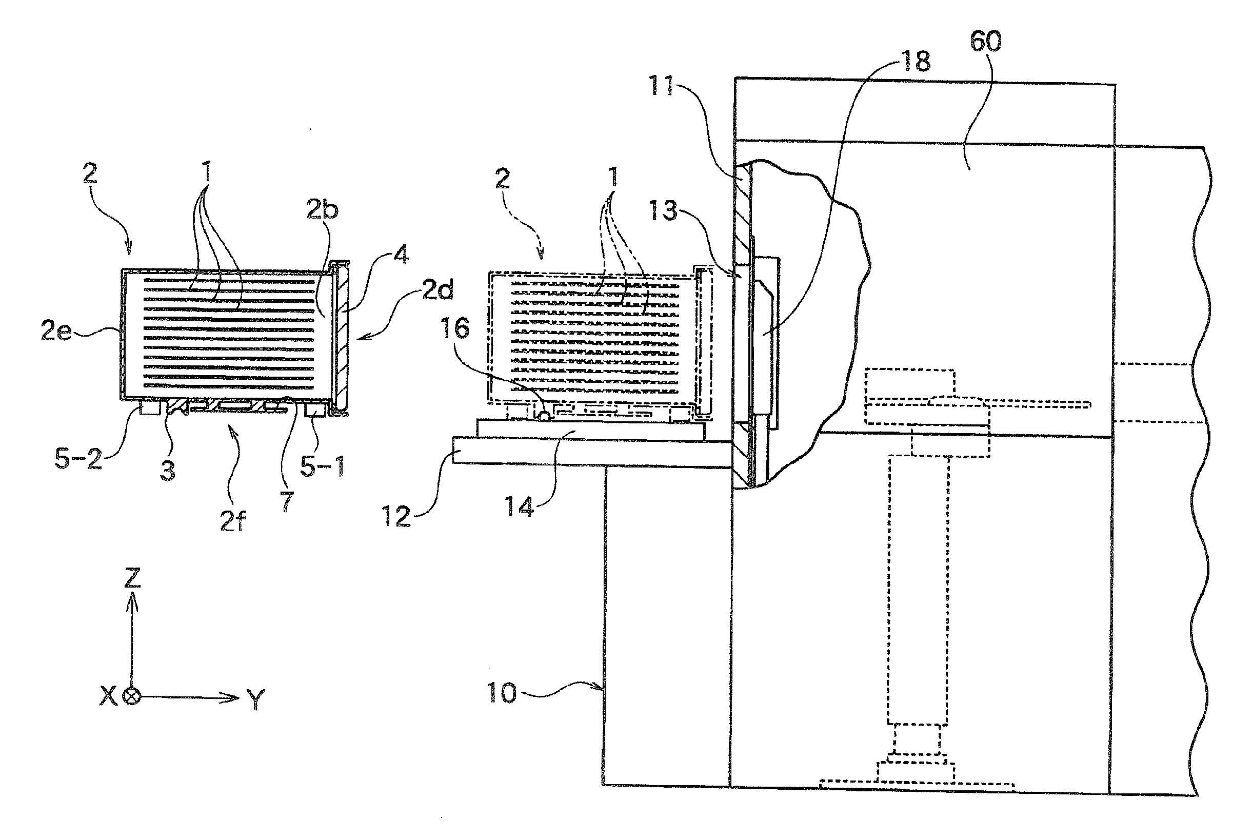
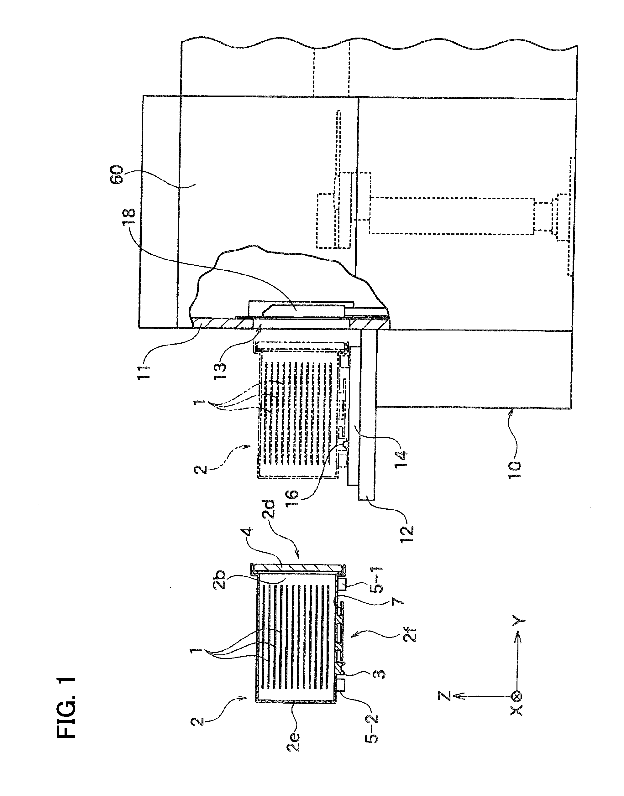
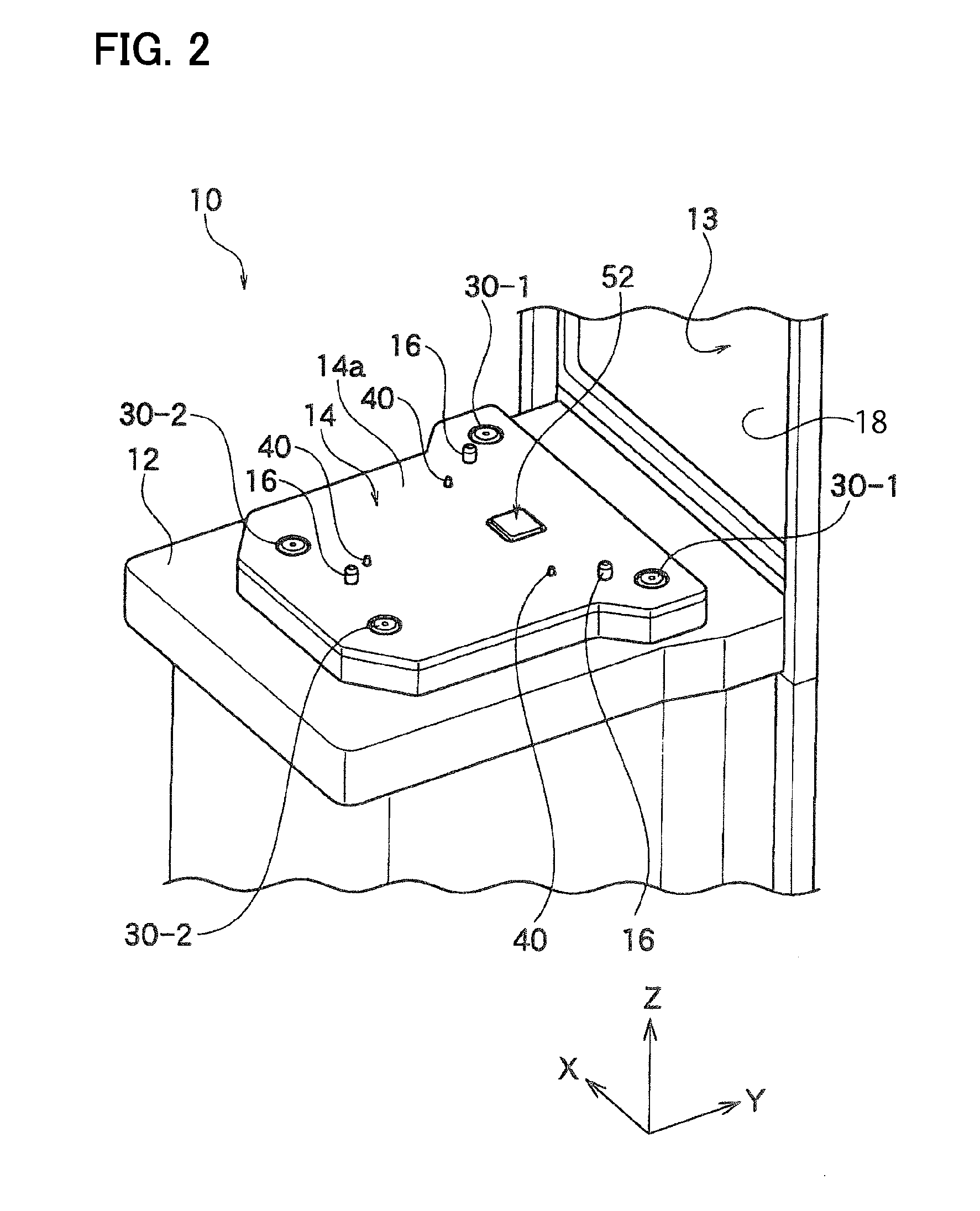
[0055]As shown in FIG. 1, a load port apparatus 10 as a gas purge apparatus according to one embodiment of the present invention is connected to an EFEM 60 connecting a semiconductor processing apparatus and the load port apparatus 10. The load port apparatus 10 has an installation stand 12 and a movable table 14. The table 14 is movable in the Y-axis direction on the installation stand 12. Note that, in the figures, the Y-axis represents a moving direction of the table 14, the Z-axis represents a vertical direction, and the X-axis represents a direction vertical to the Y-axis and the Z-axis.

[0056]A sealed transport container 2 can be detachably placed on a top of the table 14 in the Z-axis direction. The container 2 is comprised of a pot or a FOUP etc. for transporting a plurality of wafers 1 as storage objects while they are sealed and stored. A space for housing the wafers 1 is ...


PUM


Abstract

A gas purge apparatus, a load port apparatus, and a gas purge method are capable of filling a container with a cleaning gas without leaning the container to be purged. The first and second purge nozzles are configured to be escalated so that the first purge nozzle 30-1 contacts with the first purge port 5-1 whose distance to the regulating distance 90 is near before the second purge nozzle 30-2 contacts with the second purge port 5-2.

Description

BACKGROUND OF THE INVENTION[0001]1. Field of the Invention[0002]The present invention relates to a gas purge apparatus, a load port apparatus, and a gas purge method.[0003]2. Description of the Related Art[0004]For example, manufacturing process of semiconductors includes the following technique (bottom purge): a gas purge nozzle is arranged on an installation stand of a load port apparatus and is made contact with a gas purge port provided at a bottom part of a wafer transport container to introduce a purge gas therethrough and clean the inner atmosphere of the wafer transport container by the purge gas.[0005]Upon performing the bottom purge, the purge nozzle is moved toward the purge port to contact with the gas purge port provided at the bottom part of the wafer transport container to be purged (e.g., Patent Document 1). In this time, a plurality of the purge ports provided at the bottom part of the container may be pushed up by the purge nozzle, and the container may lean.[0006]...

Claims


Application Information

Patent Timeline
Patent Type & Authority Applications(United States)
IPC IPC(8): H01L21/673H01L21/677
CPCH01L21/67706H01L21/67389H01L21/67775H01L21/67393
Inventor IGARASHI, HIROSHIABE, TOMOSHIKATO, NOZOMU
Owner TDK CORPARATION
Why Eureka
Try Eureka