Laminating apparatus

a technology of lamination and cylinders, which is applied in the direction of lamination, electrical equipment, electrolytic capacitors, etc., can solve the problems of product damage and separation film, and achieve the effects of high-quality lamination, stable coupling, and structural simple and inexpensiv

Active Publication Date: 2016-09-22
MANZ ITAL
View PDF3 Cites 0 Cited by
  • Summary
  • Abstract
  • Description
  • Claims
  • Application Information

AI Technical Summary

Benefits of technology

[0007]An advantage is to provide a laminating apparatus of the type comprising rollers, capable of laminating flat-shaped objects with a laminating pressure which is practically constant all over the surface of the objects.
[0008]An advantage is to achieve high-quality lamination for flat objects of non-rectangular shape.
[0009]An advantage is to provide a laminating apparatus suitable for laminating flat, non-rectangular electrodes with a continuous separating film, in particular for the manufacture of electric energy accumulating devices.
[0010]An advantage is to achieve an assembly with a stable, strong coupling between electrodes and separating film, without damaging the separating film.
[0011]An advantage is to provide an apparatus that is structurally simple and inexpensive, featuring high productivity and excellent reliability.

Problems solved by technology

A problem with the roll lamination of objects of non-rectangular shape is to ensure a laminating pressure that is constant all over the surface of the object to be laminated.
If the laminating pressure (always equal to the ratio between the laminating force applied by the rollers and the surface subjected to such force) is not constant, there is the risk to make a product that has been subjected—in some areas—to an insufficient laminating pressure, such that it may be incorrectly assembled, and / or has been subjected—in other areas—to an excessive laminating pressure, with consequent possible damage to the product, in particular to the separating film, whereby the latter may lose—at least in part—the features that are necessary to manufacture a good-quality electric energy accumulating device.

Method used


Image

  • Laminating apparatus
  • Laminating apparatus
  • Laminating apparatus

Examples


Embodiment Construction

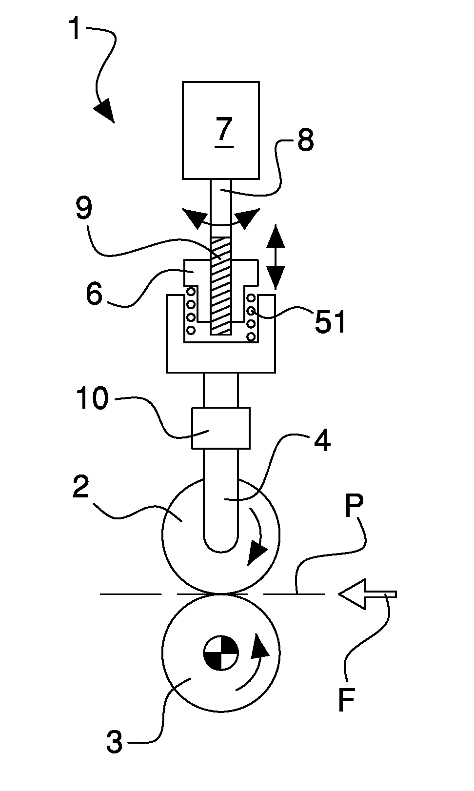
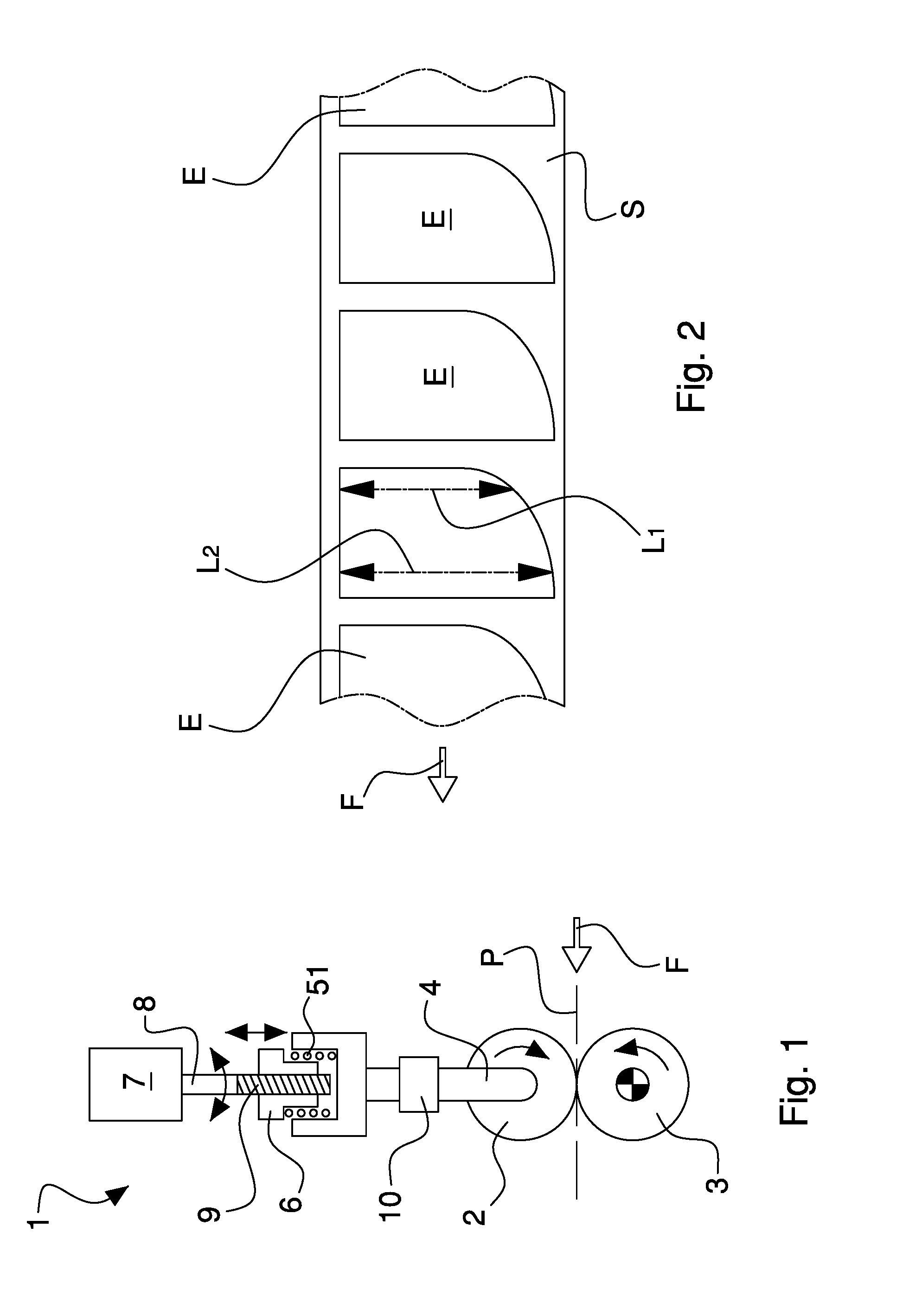
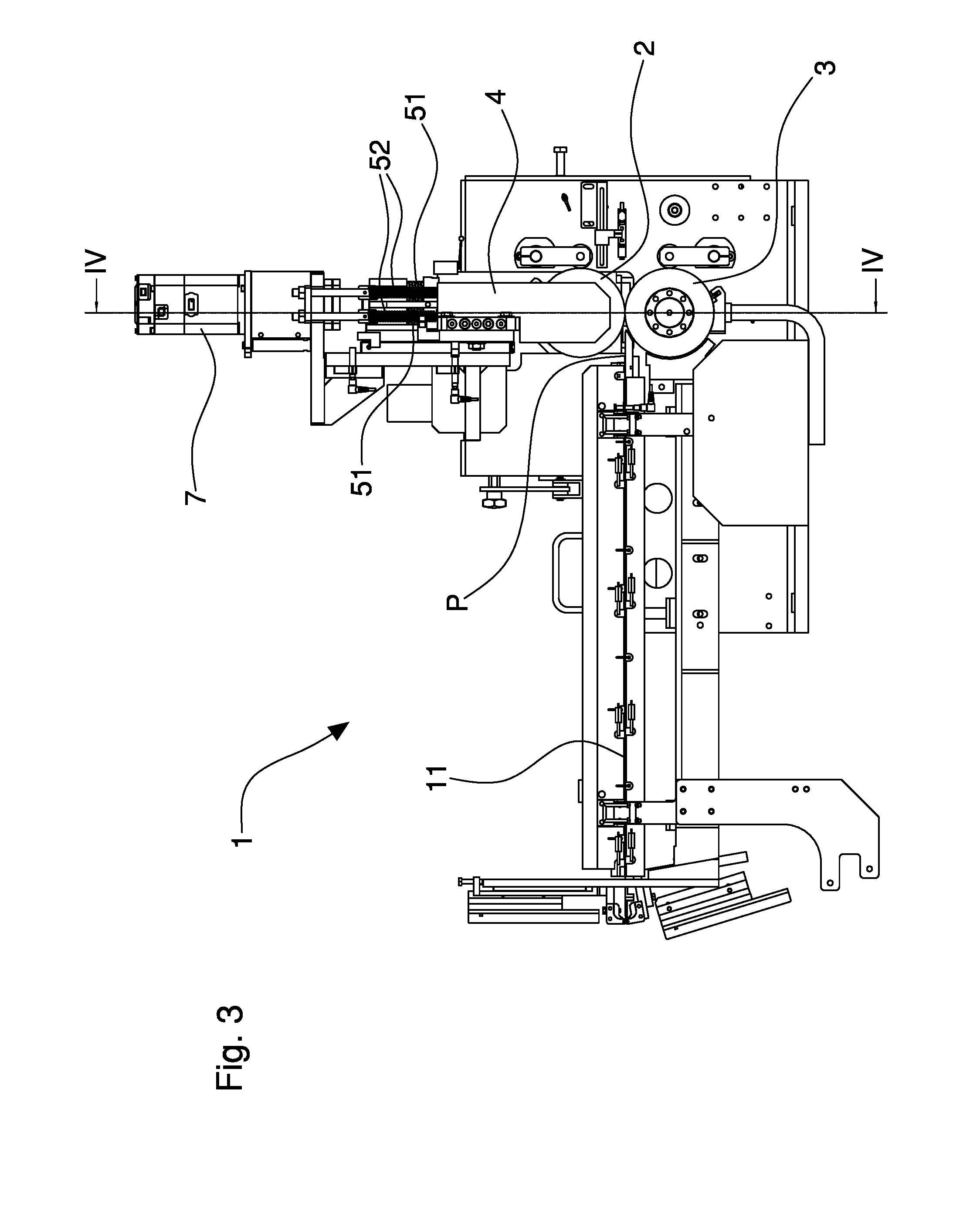
[0021]Referring to the aforesaid FIGS. 1-6, by the numeral 1 there is indicated as a whole a laminating apparatus that may be used in particular for manufacturing electric energy accumulating devices (batteries, capacitors, etc.). In particular, the laminating apparatus 1 may be used to couple at least one flat electrode E of non-rectangular shape with at least one separating film S. For the sake of clearer illustration, in the figures the same reference numerals are used to designate like elements of the several exemplary embodiments.

[0022]The apparatus 1 comprises a first (upper) laminating roller 2 and a second (lower) laminating roller 3 that are coupled together and opposite each other to define a laminating zone extending between the rollers. In particular, the two laminating rollers 2 and 3 have rotational axes that are parallel to each other (horizontal). The laminating zone may extend in width in a direction parallel to the axes of the two laminating rollers 2 and 3.

[0023]T...


PUM

PropertyMeasurementUnit
widthaaaaaaaaaa
laminating forceaaaaaaaaaa
shapeaaaaaaaaaa

Abstract

There is described a laminating apparatus for coupling electrodes of non-rectangular shape with a separating film for the manufacture of electric energy accumulating devices, wherein a pair of laminating rollers has a roller driven by an elastic arrangement loaded with a variable force adjusted by an endless screw conveyor controlled by a brushless motor, during the passage of the electrodes, so as to vary the laminating force according to the width of the electrode laminated instant by instant, in order for the laminating pressure to remain almost constant

Description

BACKGROUND OF THE INVENTION[0001]This invention relates to a laminating apparatus, in particular to an apparatus for coupling electrodes with a separating film by way of lamination.[0002]Specifically, but not exclusively, this apparatus may be used to manufacture electric energy accumulating devices.[0003]In particular, reference is made to a roll laminating apparatus that may be advantageously used to laminate flat objects of non-rectangular shape.[0004]A problem with the roll lamination of objects of non-rectangular shape is to ensure a laminating pressure that is constant all over the surface of the object to be laminated. Indeed, when an object of non-rectangular shape passes between two laminating rollers, the width of the object subjected—instant by instant—to the laminating force applied by the rollers varies depending on the shape of the object.[0005]If the laminating pressure (always equal to the ratio between the laminating force applied by the rollers and the surface subj...

Claims


Application Information

Patent Timeline
Patent Type & Authority Applications(United States)
IPC IPC(8): H01M10/04H01M6/02H01G9/00H01M6/00
CPCH01M10/0436H01M10/0413H01G9/0029H01M6/005H01M6/02H01M10/0404Y02E60/10Y02P70/50B32B37/0015B32B37/0023B32B37/223H01M4/02H01M10/0585B21B37/60B32B37/0053B32B37/10B32B37/1054B65H2404/1441B65H2511/224
Inventor SALE, MASSIMILIANOVIVARELLI, MARCO
Owner MANZ ITAL
Why Eureka
Try Eureka