System for transmitting and receiving a power line communication signal over the power bus of a power electronic converter

a power electronic converter and power bus technology, applied in the field of power electronic converters, can solve the problems of high manufacturing cost, cumbersome replacement of power electronic modules, and critical ageing of fibres under high voltage stress

Active Publication Date: 2016-09-22
ABB (SCHWEIZ) AG
View PDF6 Cites 10 Cited by
  • Summary
  • Abstract
  • Description
  • Claims
  • Application Information

AI Technical Summary

Benefits of technology

[0017]The present invention takes advantage of using the existing electric power buses for transmission of

Problems solved by technology

However, this solution requires a high number of cables and connectors, which leads to high manufacturing costs and mak

Method used


Image

  • System for transmitting and receiving a power line communication signal over the power bus of a power electronic converter
  • System for transmitting and receiving a power line communication signal over the power bus of a power electronic converter
  • System for transmitting and receiving a power line communication signal over the power bus of a power electronic converter

Examples


Embodiment Construction

[0005]Alternative communication technologies with simple and space saving structure by using existing components of the power electronic converter are still of interest and the present invention introduces such an alternative.

[0006]It is an objective of the invention to provide an alternative solution to the wireless transmission of the communication signal, which overcomes the problems of optical fibres as described before. This objective is achieved by a method and a device according to the independent claims. Preferred embodiments are evident from the dependent patent claims.

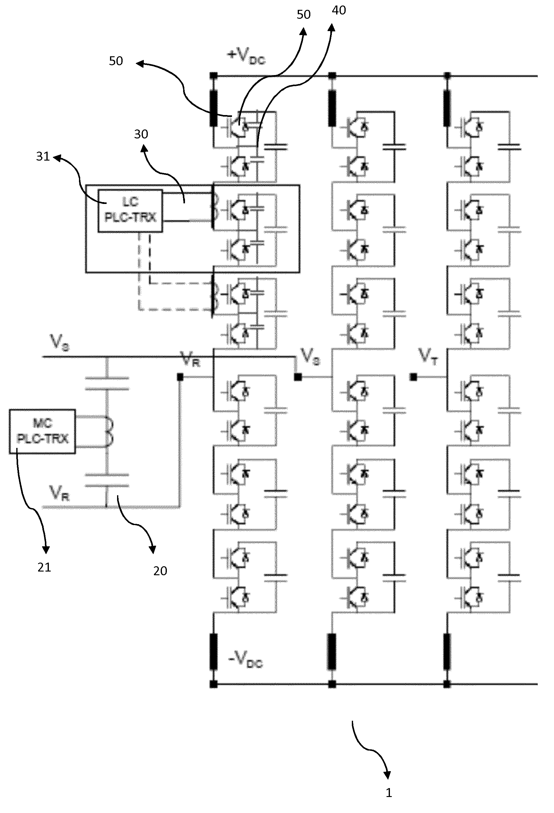
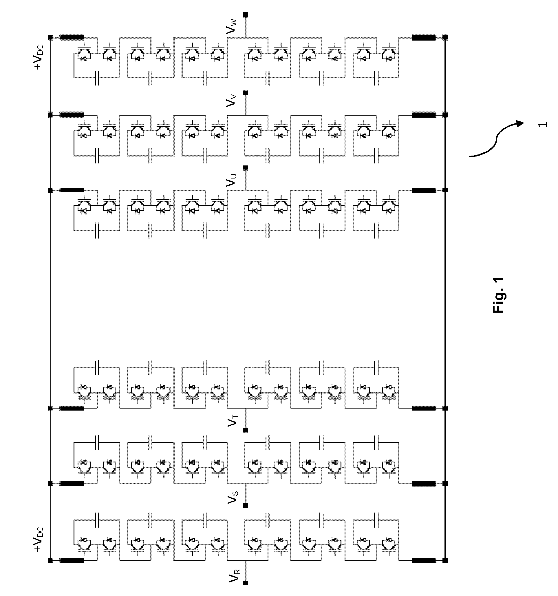
[0007]The present invention provides a communication system for transmitting and / or receiving a communication signal through a power conductor of a power electronic converter with a plurality of converter modules, comprising a transceiver adapted to modulate the communication signal on a communication signal frequency band, and a coupler connected to the power conductor and adapted to couple the modulated com...


PUM


Abstract

The present invention is concerned with a system for transmitting and/or receiving the control and sensing signals between the control units and the power electronic components. The system according to the present invention comprises: a transceiver adapted to modulate the communication signal on a communication signal frequency band, and a coupler connected to the power conductor and adapted to couple the modulated communication signal to the power conductor. The present invention also concerns a method for transmitting and receiving the control and sensing signals.

Description

FIELD OF THE INVENTION[0001]The present invention relates to the field of power electronic converters, in particular to a communication system for exchanging the control and sensing signals between the control units and the power electronic components. The present invention also concerns methods to facilitate such connections.BACKGROUND OF THE INVENTION[0002]The conventional communication networks in power electronic converters use optical fibres for transmitting power electronic control and sensing signals. When the communication signals are carried on optical fibres, the fast gate control (firing) signals can be reliably transmitted and withstand large voltages.[0003]However, this solution requires a high number of cables and connectors, which leads to high manufacturing costs and makes replacements of power electronic modules cumbersome. Also, ageing of fibres under high voltage stress may be critical.[0004]WO 2006 / 039823, US 2012 / 207138 and WO 2012 / 143222 propose the use of wire...

Claims


Application Information

Patent Timeline
IPC IPC(8): H04B3/56H02M5/458
CPCH04B3/56H02M5/4585H04B2203/5445H04B2203/5491H04B2203/5412H04B2203/5483H04B2203/5466H03K17/605H03K17/61H03K2217/0081H02M1/088H02M1/0003H02M7/4835
Inventor DZUNG, DACFEYCOTTET, DIDIERROUND, SIMON DOUGLAS
Owner ABB (SCHWEIZ) AG
Why Eureka
Try Eureka