Pilot-Aided Coherent Receiver for Optical Communications

a receiver and optical communication technology, applied in the direction of digital transmission, electromagnetic transmission, error prevention, etc., can solve the problems of phase noise and diminish the influence of noise on the received pilot amplitude, and achieve the effect of more accurate equalization of optical signals

Active Publication Date: 2016-09-22
MITSUBISHI ELECTRIC RES LAB INC
View PDF0 Cites 15 Cited by
  • Summary
  • Abstract
  • Description
  • Claims
  • Application Information

AI Technical Summary

Benefits of technology

[0009]Some embodiments of the invention are based on realization that pilot-aided equalization can be advantageously used for optical signals, especially for the equalization of the densely modulated optical signals, such as dual-polarization (DP) 64QAM and DP-256QAM. This is because the decrease of the bit rate due to the pilot symbols can be compensated by the increase of the modulation order of the optical signals due to more accurate equalization of the optical signals.

Problems solved by technology

While joint equalization is sufficient for wireless systems, the high levels of phase noise, and the need for parallel processing in optical systems, necessitates the separation of amplitude equalization and the estimation of carrier phase.
In addition, the separate equalization allows using multiple pilot symbols, e.g., by averaging the error over several pilots, therefore diminishing the influence of noise on the received pilot amplitude.

Method used


Image

  • Pilot-Aided Coherent Receiver for Optical Communications
  • Pilot-Aided Coherent Receiver for Optical Communications
  • Pilot-Aided Coherent Receiver for Optical Communications

Examples


Embodiment Construction

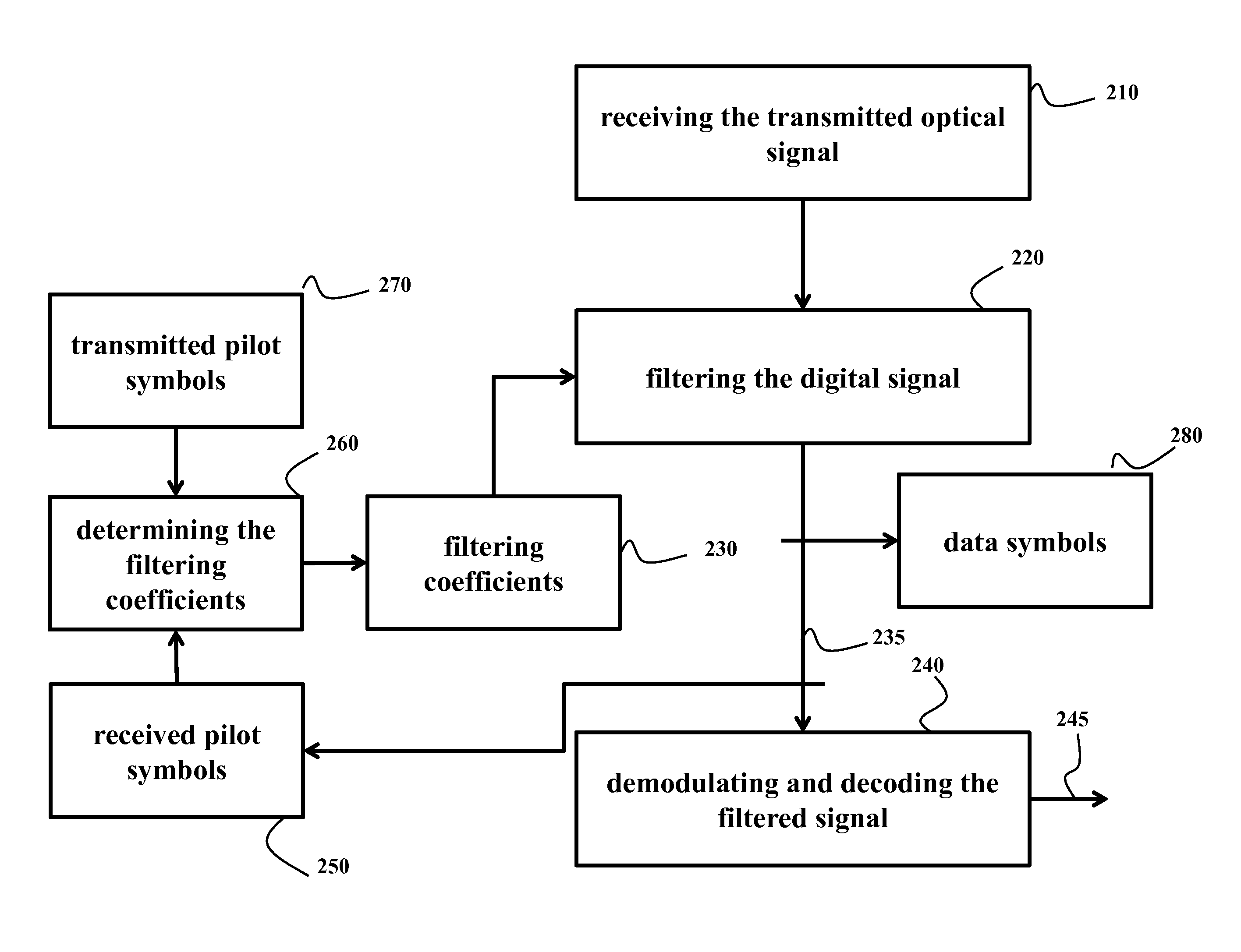
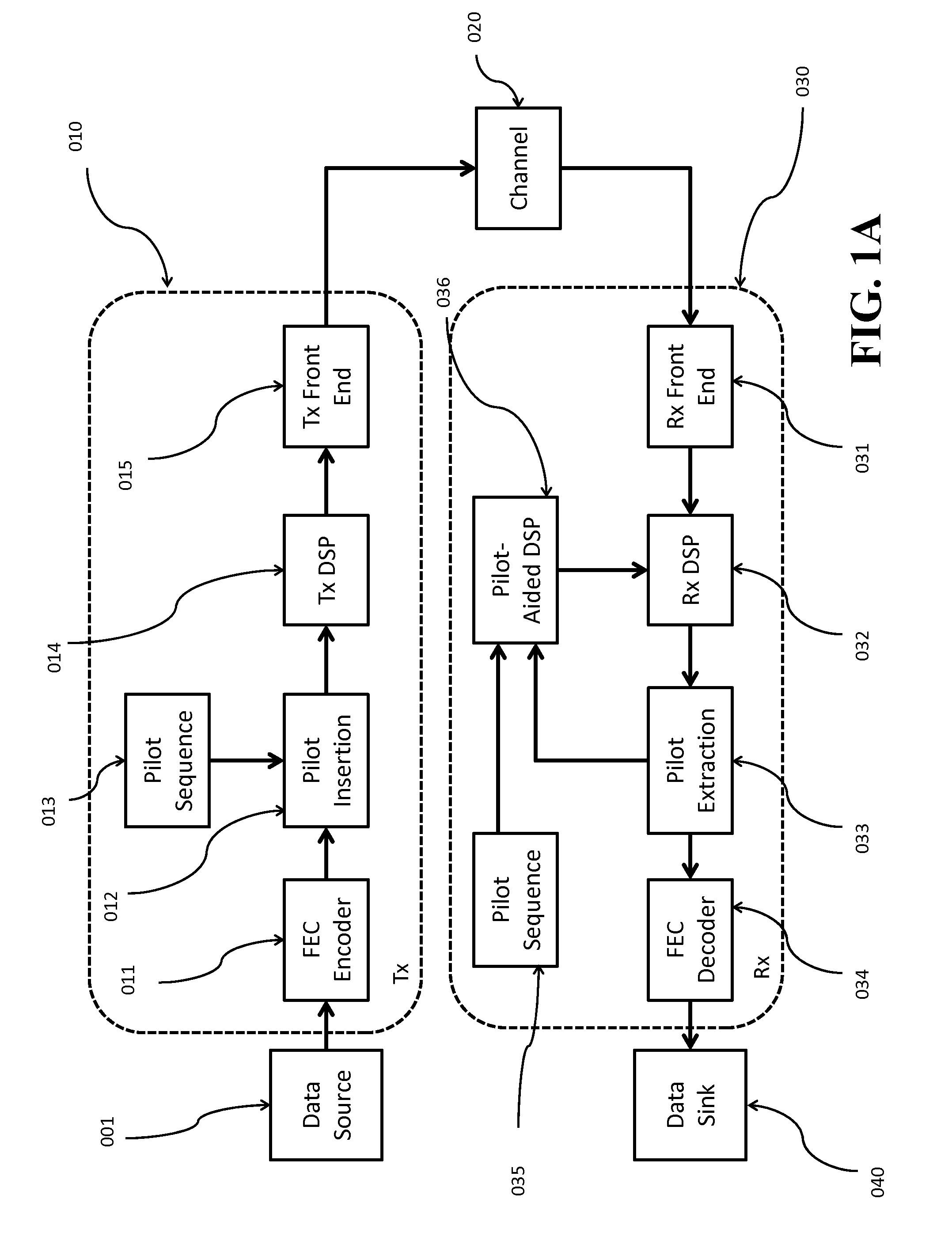
[0032]FIG. 1A shows a block diagram of a pilot-aided optical communications system according to some embodiments of the invention. Data from a source (001) are sent to a transmitter (Tx) (010). For example, the data are sent to an optional forward error correction (FEC) encoder (011) and then the data are sent to a pilot insertion block (012), where pilot symbols from a pilot sequence (013) are added at some pre-determined rate to produce a signal including a set of data symbols and a set of pilot symbols with known amplitudes and phases. After insertion of the pilot symbols, the signal undergoes digital signal processing (DSP) (014). In some embodiments, the DSP also performs other functions such as mapping, filtering and pre-equalization. The signal is then sent to the transmitter front end (015), where analog operations such as amplification, filtering, modulation and up-conversion occur, and then transmitted over an optical channel (020) to a receiver (Rx) (030).

[0033]At the rec...


PUM


Abstract

A method decodes an optical signal transmitted over an optical channel from a transmitter to a receiver. The receiver receives the transmitted optical signal to produce a digital signal including data symbols and pilot symbols, and determines filtering coefficients based on an error between amplitudes of the received pilot symbols and amplitudes of transmitted pilot symbols, while ignoring errors between phases of the received pilot symbols and phases of the transmitted pilot symbols. The amplitudes and the phases of the transmitted pilot symbols are known at the transmitter and the receiver. The receiver filters the digital signal according to the filtering coefficients to produce a filtered signal with equalized amplitude and an unconstrained phase demodulates and decodes the filtered signal to produce an estimate of the transmitted optical signal.

Description

RELATED APPLICATIONS[0001]This application claims priority under 35 U.S.C. §119(e) from U.S. provisional application Ser. No. 62 / 134,117 filed on Mar. 17, 2015, which is incorporated herein by reference.FIELD OF THE INVENTION[0002]This invention relates generally to coherent optical communications systems, and more particularly to decoding data transmitted over an optical channel.BACKGROUND OF THE INVENTION[0003]Inaccuracies in carrier-phase estimation and amplitude equalization cause distortions, i.e., the noise enhancements, which reduce the performance of optical communications systems. In the optical communications, different algorithms are used to reduce the distortion. Those algorithms are based on a hard decision for determining the phase and amplitude of the received signal. For example, a decision-directed least-mean-square (LMS) method uses the hard decision for determining the error for the updating.[0004]However, the hard decisions can be incorrect causing suboptimal pha...

Claims


Application Information

Patent Timeline
Patent Type & Authority Applications(United States)
IPC IPC(8): H04B10/69H04B10/079H04L1/00
CPCH04B10/6971H04B10/0795H04L1/0036H04B10/6972H04B10/612H04B10/6165H04L25/03019H04L25/0224
Inventor MILLAR, DAVID SKOIKE-AKINO, TOSHIAKIPAJOVIC, MILUTIN
Owner MITSUBISHI ELECTRIC RES LAB INC
Why Eureka
Try Eureka