Fluid reservoir for an aerosol generation device, combination of fluid reservoir and primary fluid package, and aerosol generation device for use with the fluid reservoir

a technology of aerosol and fluid reservoir, which is applied in the field of fluid reservoir, can solve the problems of reducing the effectiveness of aerosol treatment, posing a health risk to patients receiving aerosol treatment, and insufficient thorough cleaning procedure, and achieves the effects of convenient opening of the interface portion, high degree of accuracy and precision, and high aerosol dosage precision

Active Publication Date: 2016-09-29
PARI PHARMA GMBH
View PDF8 Cites 9 Cited by
  • Summary
  • Abstract
  • Description
  • Claims
  • Application Information

AI Technical Summary

Benefits of technology

[0113]The aerosol generation device according to the invention provides the advantageous effects already described in detail above for the fluid reservoir of the invention. In particular, the aerosol generation device of the invention allows for a contamination of the generated aerosol to be reliably prevented, thereby ensuring an effective aerosol treatment.
[0114]The aerosol generation device may further have an opening element, such as a thorn, a hollow needle, a collar, a conduit or the like, for opening the interface portion of the fluid reservoir and guiding the fluid from the fluid reservoir into the interior of the aerosol generation device. The opening element may be provided with a sharp edge or tip portion, such as a blade element or the like, at a top portion thereof, in order to facilitate opening of the interface portion of the fluid reservoir and draining of the fluid from the fluid reservoir. Such a configuration is particularly advantageous for use with a fluid reservoir with an interface portion having a wall element sealing the end of the fluid reservoir, as described above.
[0115]The opening element of the aerosol generation device may be configured for opening a valve element, such as a ball valve, a valve diaphragm or the like, provided in the interface portion of the fluid reservoir for regulating fluid flow through the fluid reservoir into the aerosol generation device.
[0116]The opening element may have a substantially cylindrical shape. A conduit, channel or the like may be provided in the opening element for guiding fluid from the fluid reservoir into the interior of the aerosol generation device. The conduit or channel may have a substantially cylindrical shape. Alternatively, the opening element and / or the conduit or channel may have a rectangular, square, triangular or other polygonal cross-sectional shape. A substantially cylindrical shape of the opening element provides the advantage of enabling a particularly uniform opening of the fluid reservoir, thus allowing for a steady opening process. A substantially cylindrical shape of the conduit or channel offers the advantage of enabling a particularly homogeneous flow of the fluid through the opening element into the aerosol generation device.
[0117]The attachment portion of the aerosol generation device may be provided with a valve element, such as a ball valve or the like, for regulating fluid flow through the fluid reservoir into the interior of the aerosol generation device. In this way, the fluid flow into the device can be controlled with a particularly high degree of accuracy and precision, thereby ensuring a high aerosol dosage precision.
[0118]The aerosol generation device may further comprise a protective cap or lid for closing or sealing the attachment portion. In this way, a contamination of the aerosol generation device by ambient air entering the device can be reliably prevented when the device is not in use. The protective cap or lid may be attached to the aerosol generation device, e.g., by a hinge, integrally formed with the aerosol generation device or provided as a separate entity. The structure of the protective cap may be similar to that of the fluid reservoirs described above. In particular, the structure of an interface portion of the protective cap may be the same as that of the interface portions of these fluid reservoirs. The protective cap may differ from these fluid reservoirs in that it has a wall sealing the end of the protective cap so as to enable a reliable closing and sealing of the attachment portion.

Problems solved by technology

However, for some fluids even such a thorough cleaning procedure is not sufficient.
Nevertheless, there remains a risk that a used fluid reservoir is accidentally reused, potentially causing a contamination of the aerosol, thereby reducing the effectiveness of the aerosol treatment or even posing a health risk to a patient receiving the aerosol treatment.

Method used


Image

  • Fluid reservoir for an aerosol generation device, combination of fluid reservoir and primary fluid package, and aerosol generation device for use with the fluid reservoir
  • Fluid reservoir for an aerosol generation device, combination of fluid reservoir and primary fluid package, and aerosol generation device for use with the fluid reservoir
  • Fluid reservoir for an aerosol generation device, combination of fluid reservoir and primary fluid package, and aerosol generation device for use with the fluid reservoir

Examples


first embodiment

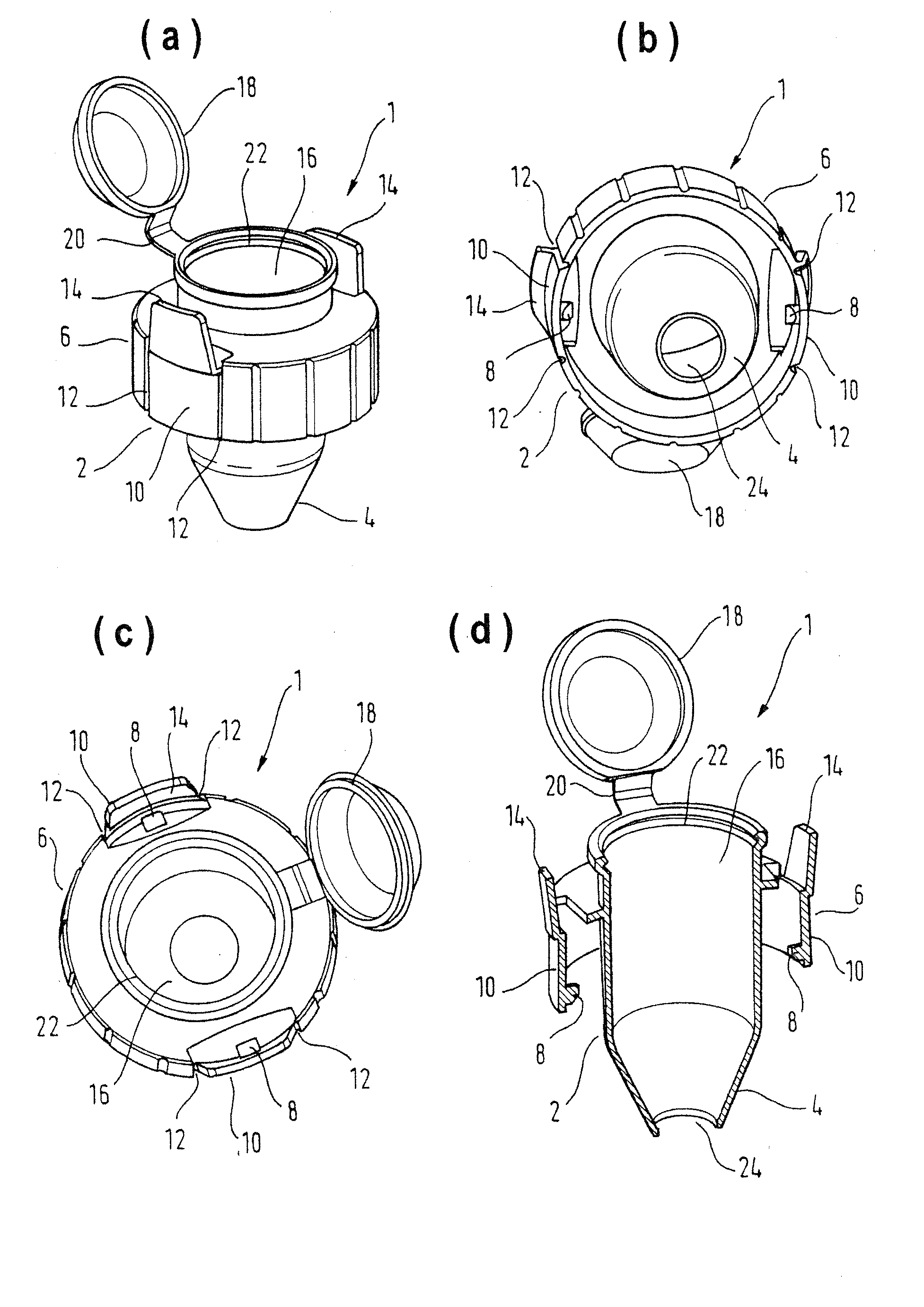
[0131]FIGS. 1(a) to (d) show schematic views of a fluid reservoir 1 according to a currently preferred first embodiment of the invention.

[0132]The fluid reservoir 1 shown in FIG. 1 has an interface portion 2 arranged at an end 4 of the fluid reservoir 1 for attaching the fluid reservoir 1 to an aerosol generation device, which will be described later. The interface portion 2 comprises a collar 6 with a pair of pins 8, e.g., detent pins or locking pins, extending from an inner surface thereof. Each of portions 10 of the collar 6 on which the pins 8 are provided is connected to the remainder of the collar 6 through two weakened portions 12, facilitating removal of the collar portions 10 from the collar 6. Further, each of the collar portions 10 is integrally formed with a flap or tab 14 extending upwards from the collar portions 10 in an axial direction of the fluid reservoir 1, i.e., in a direction of fluid flow in the fluid reservoir 1.

[0133]The pins 8 provided on the collar 6 of th...

second embodiment

[0167]FIG. 4 shows a protective cap 180 for closing or sealing an attachment portion of an aerosol generation device, e.g., the aerosol generation device of the first or the By attaching the protective cap 180 to the attachment portion, a contamination of the aerosol generation device by ambient air entering into the device can be reliably prevented when the device is not in use.

[0168]The structure of the protective cap 180 is similar to that of the fluid reservoir 1 according to the first embodiment of the present invention, as will be detailed in the following.

[0169]In particular, the structure of an interface portion 182 of the protective cap 180 is identical to that of the interface portion 2 of the fluid reservoir 1 of the first embodiment shown in FIG. 1. Therefore, a detailed description thereof is omitted. The protective cap 180 differs from the fluid reservoir 1 in that it has a wall 192 sealing the end 184 of the protective cap 180 and does not have a fluid reservoir inte...

third embodiment

[0171]FIG. 6 shows a schematic view of a pouch 150 made of plastic, such as polyethylene, containing an adapter 200 of a fluid reservoir according to a currently preferred third embodiment of the present invention and a primary fluid package 250.

[0172]The structure of the adapter 200 is similar to that of the lower portion of the fluid reservoir 1 (i.e., the portion of the fluid reservoir 1 closer to the end 4) according to the first embodiment shown in FIG. 1, as will be explained in detail below.

[0173]The structure of an interface portion 202 of the adapter 200 for attaching the adapter 200 to an aerosol generation device is substantially identical to that of the interface portion 2 of the fluid reservoir 1 of the first embodiment. Therefore, a detailed description thereof is omitted.

[0174]The adapter 200 differs from the lower portion of the fluid reservoir 1 in the arrangement and the shape of the flaps or tabs 214. The flaps or tabs 214 are arranged at a bottom section of colla...


PUM


Abstract

The invention relates to a fluid reservoir (1, 100, 330, 400) which is attachable to an aerosol generation device for guiding a fluid from a fluid container (16, 116, 300) to the aerosol generation device. The fluid reservoir has an interface portion (2, 102, 202) arranged at the fluid reservoir for attaching the fluid reservoir to the aerosol generation device. The interface portion has a locking element (8, 10, 12, 14; 110, 114; 210, 214) configured to non-detachably lock the fluid reservoir to the aerosol generation device after attachment of the fluid reservoir to the aerosol generation device. The locking element is breakable to enable detachment of the fluid reservoir from the aerosol generation device. Further, the invention relates to a combination of the fluid reservoir and a primary fluid package (250), wherein the primary fluid package has at least one chamber (252, 254) containing a fluid therein. The invention also relates to an aerosol generation device which is configured for use with the fluid reservoir. The aerosol generation device has an attachment portion (52, 152) for receiving the interface portion of the fluid reservoir.

Description

FIELD OF THE INVENTION[0001]The invention relates to a fluid reservoir which is attachable to an aerosol generation device (nebuliser) for guiding a fluid from a fluid container to the aerosol generation device, a combination of the fluid reservoir and a primary fluid package and an aerosol generation device which is configured for use with the fluid reservoir.BACKGROUND ART[0002]Aerosols for therapeutic purposes are generated with aerosol generation devices. A conventional aerosol generation device is disclosed, for example, in US-A-2011 / 0146670. The aerosol generation device of this document comprises a fluid reservoir for receiving a fluid (i.e., medicament) to be nebulised, which is connected to the body of the device. The fluid reservoir may be integrally connected to the device. Alternatively, the fluid reservoir may be connected to the device in such a manner that it can be coupled to and uncoupled from the device.[0003]Aerosols for therapeutic purposes generally have to meet...

Claims


Application Information

Patent Timeline
Patent Type & Authority Applications(United States)
IPC IPC(8): A61M11/00A61M16/16A61M15/00
CPCA61M11/005A61M15/00A61M2202/064A61M2205/273A61M2202/0468A61M16/16A61M15/0003A61M15/0028A61M2205/276
Inventor GALLEM, THOMASHETZER, UWENEUNER, MICHAEL
Owner PARI PHARMA GMBH
Why Eureka
Try Eureka