Outer cover material for wire harness, and routing structure for wire harness

a technology of outer cover material and wire harness, which is applied in the direction of insulated conductors, cables, conductors, etc., can solve the problems of difficult to control the direction of curves, and achieve the effects of convenient positioning and fixing, high manufacturing efficiency, and convenient shape retention

Inactive Publication Date: 2016-09-29
SUMITOMO WIRING SYST LTD
View PDF10 Cites 8 Cited by
  • Summary
  • Abstract
  • Description
  • Claims
  • Application Information

AI Technical Summary

Benefits of technology

[0037]The outer cover material for a wire harness according to a first aspect of the present invention includes the coupling plates that are bent on both sides of the band-shaped central plate made of an injection molded article. The outer cover material is made square tubular by folding the central plate at the folding lines thereof that are constituted by the grooves, and thus has shape retainability in the state of being square tubular, and it is possible to make the outer cover material only of polypropylene without mixing an expensive elastomer with inexpensive polypropylene. Also, post-processing after molding is not needed, and manufacturing is highly efficient. Also, since injection molding is used, the tape wound piece that is provided at the end of the outer cover material in the length direction and to which the wire harness can be fixed by winding a tape around it, and the clip that is fixed to a fixation material such as the vehicle body panel

Problems solved by technology

Conventional corrugated tubes that are generally used as an outer cover material for a wire harness meander while being curved on b

Method used


Image

  • Outer cover material for wire harness, and routing structure for wire harness
  • Outer cover material for wire harness, and routing structure for wire harness
  • Outer cover material for wire harness, and routing structure for wire harness

Examples


Embodiment Construction

[0049]Hereinafter, embodiments of the present invention will be described with reference to the drawings.

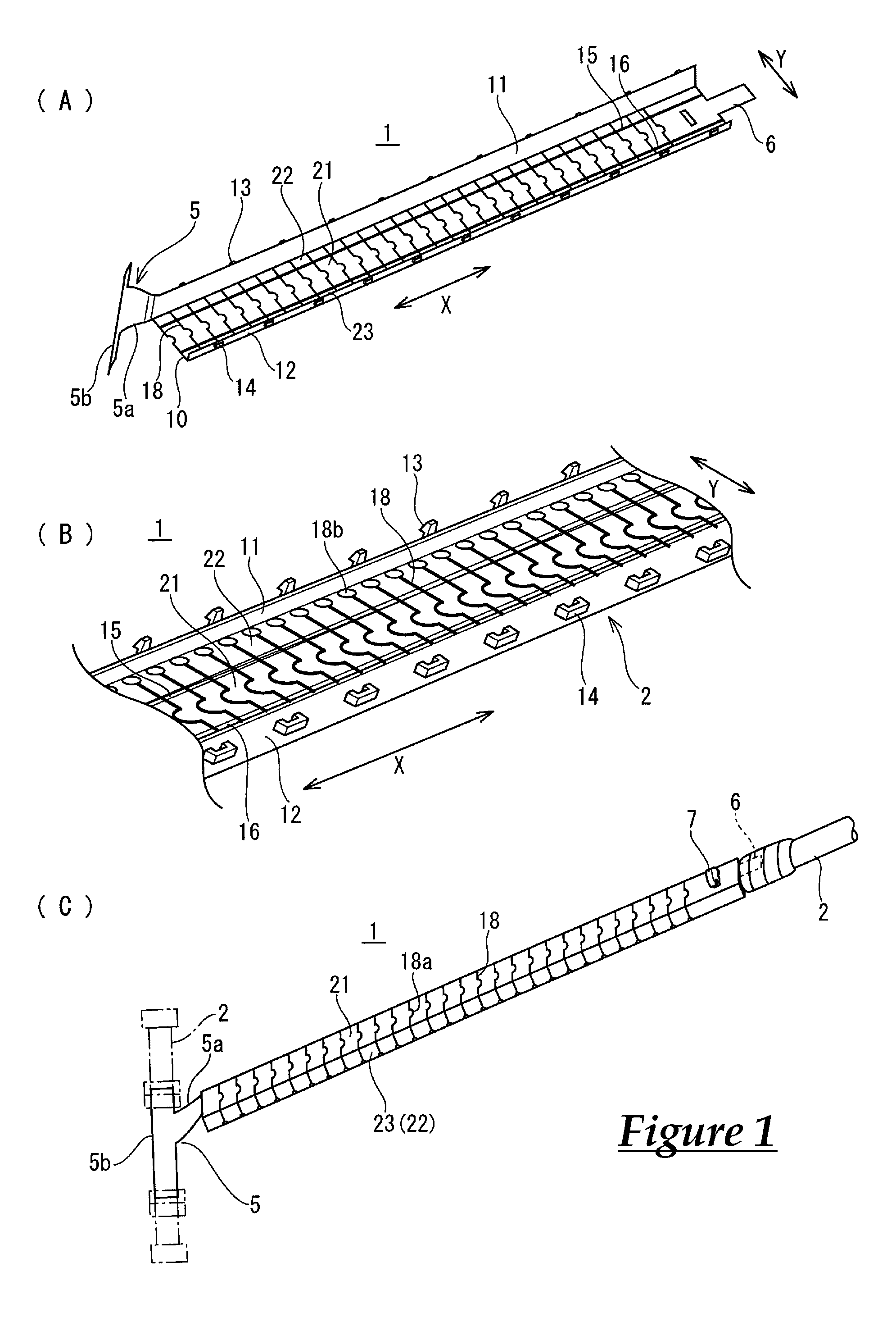
[0050]FIGS. 1 to 3 show an embodiment of an outer cover material for a wire harness according to the present invention.

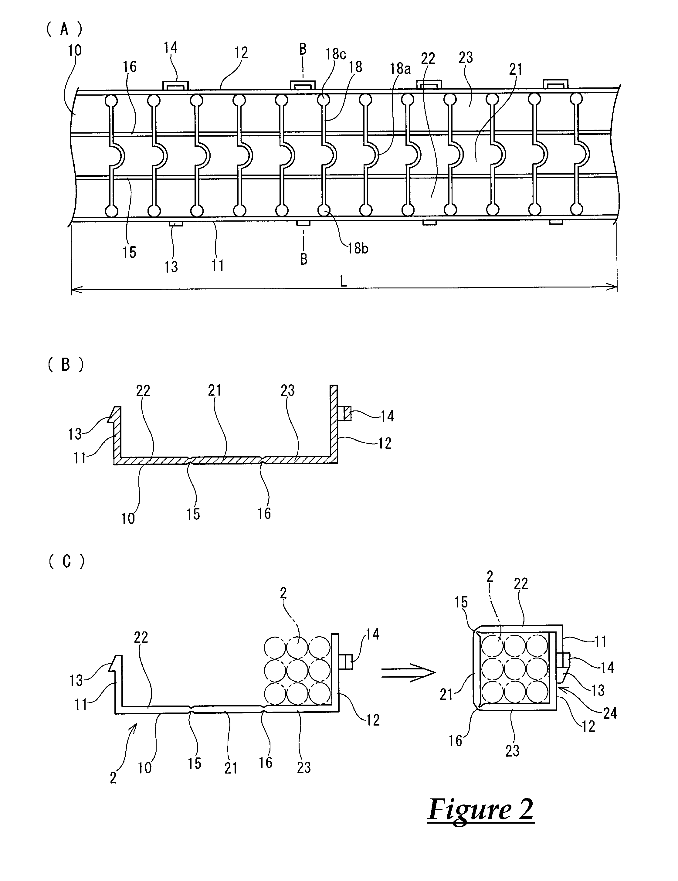
[0051]An outer cover material 1 shown in FIGS. 1 and 2 is made of an injection molded article, namely, polypropylene in the present embodiment.

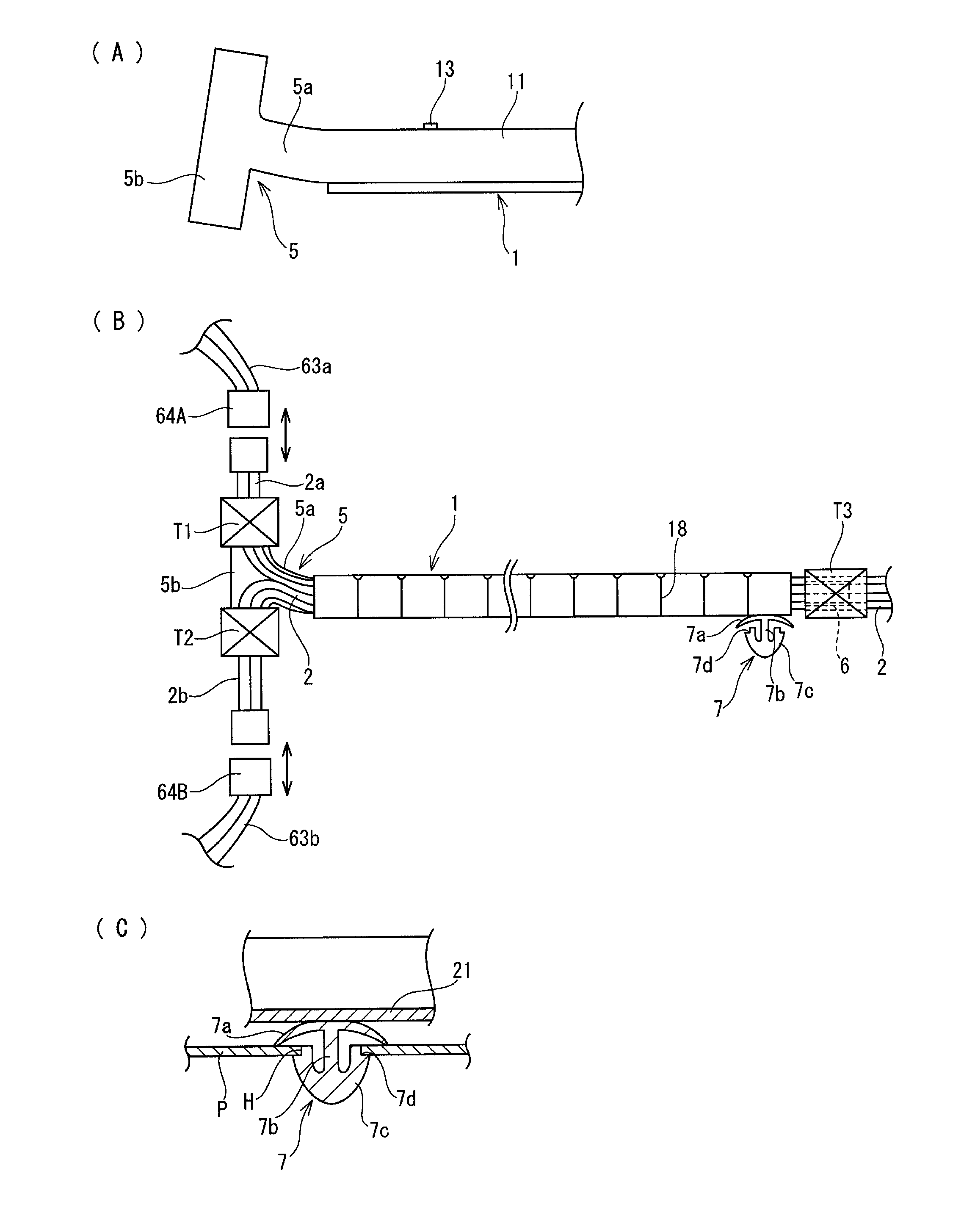
[0052]The outer cover material 1 is bent in a state in which a wire harness 2 is set therein and is assembled into a square tube so as to externally cover the wire harness 2. The outer cover material 1 is caterpillar-shaped so as to be flexible by slits 18 provided at intervals in the length direction opening and closing.

[0053]The outer cover material 1 has a pair of coupling plates 11 and 12 along two edges, in a width direction Y, of a band-shaped central plate 10, the coupling plates 11 and 12 being bent at substantially 90 degrees and protruding parallel to each other. Locking claws 13 protrude from an end of one coupl...


PUM


Abstract

A caterpillar-shaped outer cover material for a wire harness is improved. An outer cover material for a wire harness that is made of an injection molded article and is caterpillar-shaped includes coupling plates that are provided along two edges of a band-shaped central plate in a width direction so as to protrude in parallel to each other. One of the coupling plate has locking claws that are provided at intervals in a length direction protruding from an end of that coupling plate, the other of the coupling plates has locked frames to which the locking claws are respectively locked and coupled, and that protrude from an end of that coupling plate, and the central plate has folding lines constituted by two grooves that extend in the length direction at a distance in the width direction, and has slits extending in the width direction that are provided at intervals in the length direction. Furthermore, a tape wound piece to which a wire harness is to be fixed is provided at least one of two ends, in the length direction, of the one coupling plate or a member arranged between the folding lines of the central plate, and a clip for being latched to a fixation material protrudes from at least the other end.

Description

TECHNICAL FIELD[0001]The present invention relates to an outer cover material for a wire harness and a routing structure of a wire harness covered with this outer cover material, and relates in particular to an improvement of a caterpillar-shaped outer cover material, and an application of a wire harness that is covered with this outer cover material to a wire harness routing structure for sliding seats.BACKGROUND ART[0002]Wire harnesses that are routed from the floor side to a sliding seat installed in an automobile, or wire harnesses that are routed between doors and the vehicle body are repeatedly moved in accordance with the forward and backward movement of the sliding seat or opening and closing movement of the doors, and thus these wire harnesses often have an excess length, and the excess length is absorbed by the wire harnesses being bent and moved in an excess length accommodating section provided on a wire harness routing path.[0003]Outer cover materials for the wire harne...

Claims


Application Information

Patent Timeline
IPC IPC(8): B60R16/02H02G3/04H01B7/00H01B7/17B60N2/90
CPCB60R16/0215H01B7/0045H02G3/0462H01B7/17F16G13/16H02G3/0443H02G3/0487B60N2/02B60N2/06B60N2/0264
Inventor KATOU, SHINJISAKAKIBARA, YOSHIKAZU
Owner SUMITOMO WIRING SYST LTD
Why Eureka
Try Eureka