
Propulsion system for aquatic vessels

a technology for aquatic vessels and propulsion systems, applied in the direction of propulsive elements, roller bearings, hull reinforcements, etc., can solve the problems of insufficient ventilation and/or cooling of motors, insufficient installation of known magnus rotors for servicing personnel, and potentially tedious and cumbersome assembly and installation of known magnus rotors on the deck of aquatic vessels to achieve the effect of improving the propulsion system

Active Publication Date: 2016-09-29
NORSEPOWER OY
View PDF6 Cites 6 Cited by
  • Summary
  • Abstract
  • Description
  • Claims
  • Application Information

AI Technical Summary

Benefits of technology

The present invention overcomes the problems of prior art by providing proper air ventilation and cooling for the motor and other internal components. It also allows for easier access to the motor and other components, making maintenance more convenient. The design includes a horizontal axis for the motor and a vertical axis for the bearing arrangements, which reduces the risk of damage to the belt drives during maintenance.

Problems solved by technology

However, implementations of known Magnus rotors locate associated motors in restricted spaces, resulting in the motors being insufficiently ventilated and / or cooled.
Moreover, the implementations of known Magnus rotors are problematic for servicing personnel, when accessing associated motors or other internal components of the Magnus rotors during service or overhaul routines.
Assembly and installation of the known Magnus rotors onto a deck of an aquatic vessel is potentially tedious and cumbersome on account of specific constructional limitations of such aquatic vessels.

Method used


Image

  • Propulsion system for aquatic vessels
  • Propulsion system for aquatic vessels
  • Propulsion system for aquatic vessels

Examples


Embodiment Construction

[0047]The following detailed description illustrates embodiments of the present disclosure and ways in which it can be implemented. Although the best mode of carrying out the present disclosure has been disclosed, persons skilled in the art would recognize that other embodiments for carrying out or practicing the present disclosure are also possible.

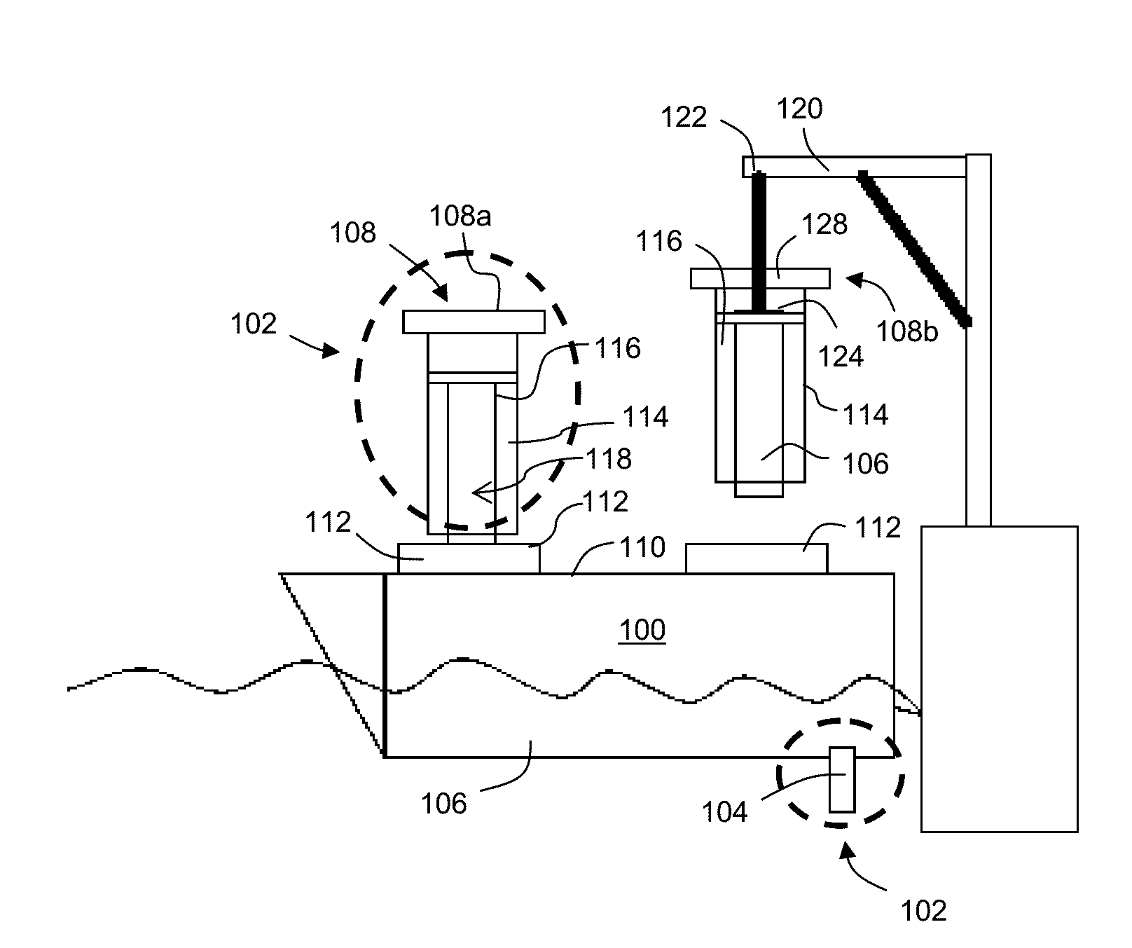
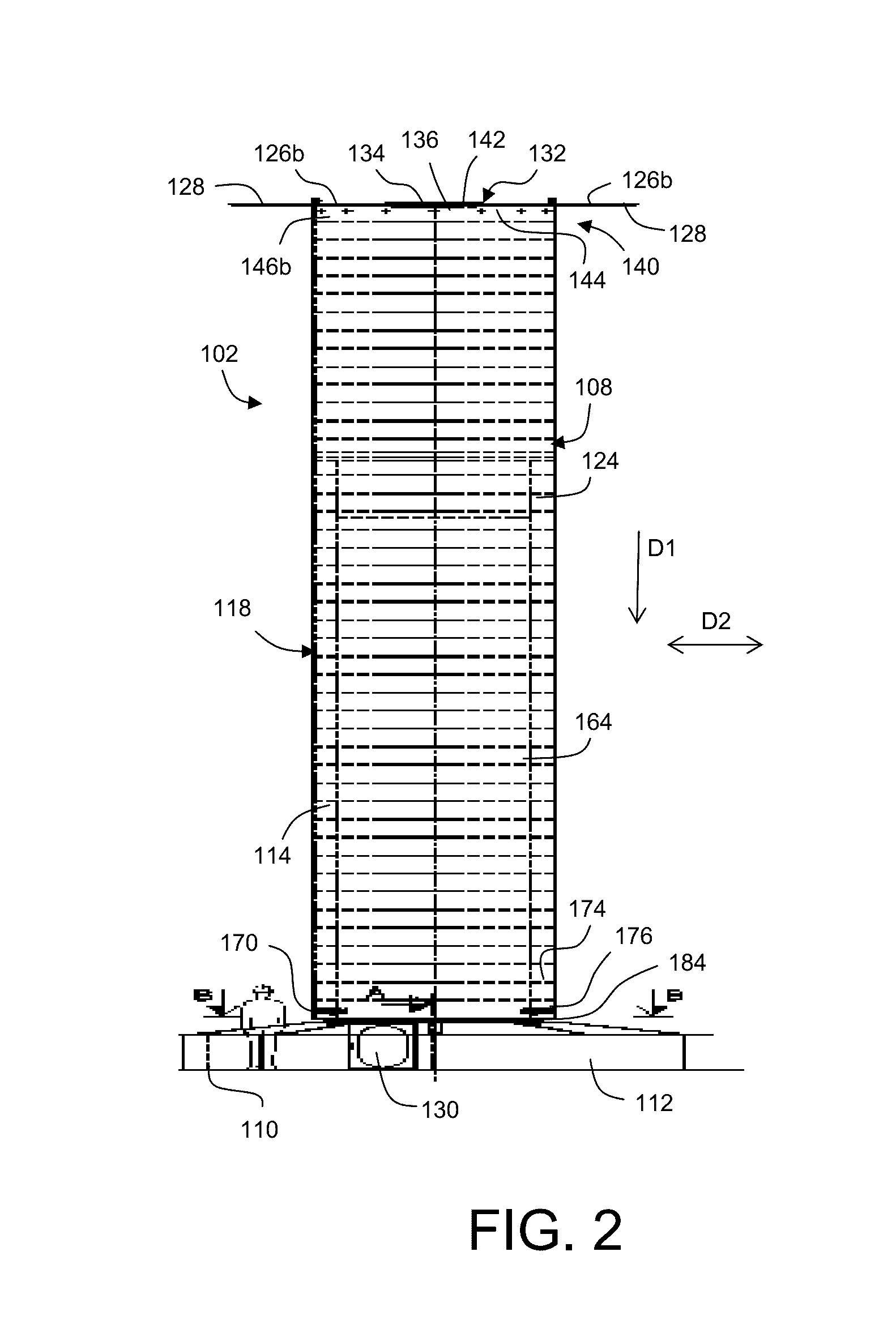
[0048]Embodiments of the present disclosure provide a propulsion system for an aquatic vessel. The propulsion system includes a plurality of Magnus-type rotors and a drive arrangement for rotating the plurality of Magnus-type rotors. The plurality of Magnus-type rotors are operable to rotate about corresponding substantially upright axes, thereby producing a Magnus effect to propel the aquatic vessel. The Magnus effect is herewith defined as a thrust acting on a rotating body in a moving airstream, such as wind, wherein the thrust acts substantially perpendicularly to a direction of the moving airstream.

[0049]The propulsion system also i...


PUM


Abstract

A propulsion system (102) for an aquatic vessel (100) is provided. The propulsion system includes a plurality of Magnus-type rotors (108) and a drive arrangement (147) for rotating the plurality of Magnus-type rotors. The plurality of Magnus-type rotors are operable to rotate about corresponding substantially upright axes. The propulsion system also includes a control arrangement (150) for controlling the drive arrangement to vary rates of rotations of the plurality of Magnus-type rotors. Each of the plurality of Magnus-type rotors includes a hollow region (116) therein. Each of the Magnus-type rotors is rotationally supported onto a support arrangement (118) which extends into the hollow region. The drive arrangement includes at least one motor (148) disposed in the hollow region and located outside the support arrangement such that the at least one motor is accessible for maintenance. Furthermore, the at least one Magnus-type rotor includes a ventilation aperture arrangement (132) for enabling an upward movement of air to occur in operation within the at least one Magnus-type rotor for ventilating and cooling the drive arrangement and / or other internal components.

Description

TECHNICAL FIELD[0001]The present disclosure generally relates to propulsion systems for aquatic vessels, for example to propulsion systems employing Magnus-type rotors for propelling aquatic vessels. Moreover, the present invention relates to methods of installing the propulsion systems into the aquatic vessels.BACKGROUND[0002]Recently, attempts are being made in marine industry to utilize wind power to propel aquatic vessels. A conventional propulsion system for an aquatic vessel includes one or more submerged propellers for propelling the aquatic vessel, and may further include multiple Magnus rotors for supplementing the propellers. The Magnus rotors are operable rotate about corresponding substantially upright axes to produce a Magnus effect for propelling the aquatic vessel. The Magnus effect is defined as a thrust acting on a rotating body in a moving airstream, such as wind, wherein the thrust acts perpendicularly to a direction of the moving airstream.[0003]Magnus rotors are...

Claims


Application Information

Patent Timeline
Patent Type & Authority Applications(United States)
IPC IPC(8): B63H9/02F16C23/08F16C19/38
CPCB63H9/02F16C2326/30F16C23/08F16C19/38B63B3/70B63H2023/0216Y02T70/5236
Inventor LEVANDER, KAIRISKI, TUOMASHUHTINEN, HEIKKI JUHANI
Owner NORSEPOWER OY
Learn More