A Mechanical Transmission For a Mail Stacker Unit With a Clutch Brake and Elliptical Gearing

a technology of clutch brake and transmission gear, which is applied in the direction of article delivery, thin material processing, sorting, etc., can solve the problems of consuming energy continuously requiring braking energy to be removed, and consuming energy in order to power the electronics, etc., to reduce the number of sensors and their complexity, simplify any adjustment of the stacking cycle, and limit the electricity consumption of the stacker unit

Inactive Publication Date: 2016-09-29
SOLYSTIC
View PDF9 Cites 3 Cited by
  • Summary
  • Abstract
  • Description
  • Claims
  • Application Information

AI Technical Summary

Benefits of technology

[0023]This arrangement also makes it possible to limit the number of sensors and their complexity, to simplify any adjustment of the stacking cycle, and to limit the electricity consumption of the stacker unit.

Problems solved by technology

Such an electric motor with an electronic variable speed drive is very costly, limited in power, and complex to operate.
In addition, it consumes energy continuously in order to power the electronics, and requires braking energy to be removed.
It also poses problems of electronic reliability and of electromagnetic compatibility.

Method used


Image

  • A Mechanical Transmission For a Mail Stacker Unit With a Clutch Brake and Elliptical Gearing
  • A Mechanical Transmission For a Mail Stacker Unit With a Clutch Brake and Elliptical Gearing
  • A Mechanical Transmission For a Mail Stacker Unit With a Clutch Brake and Elliptical Gearing

Examples


Embodiment Construction

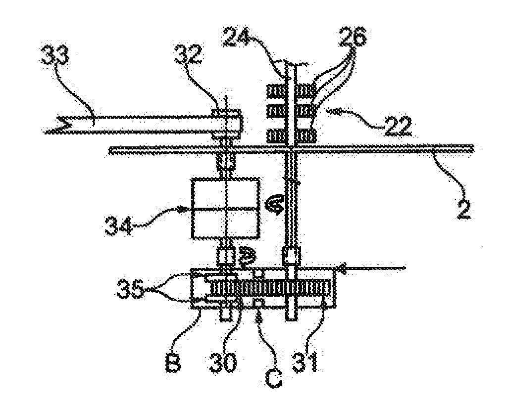
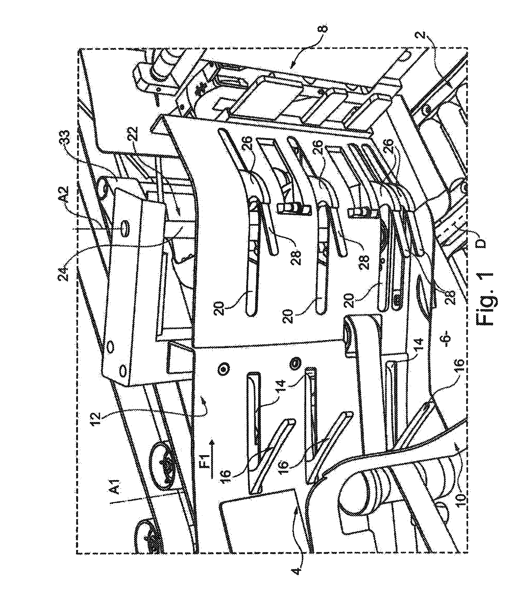
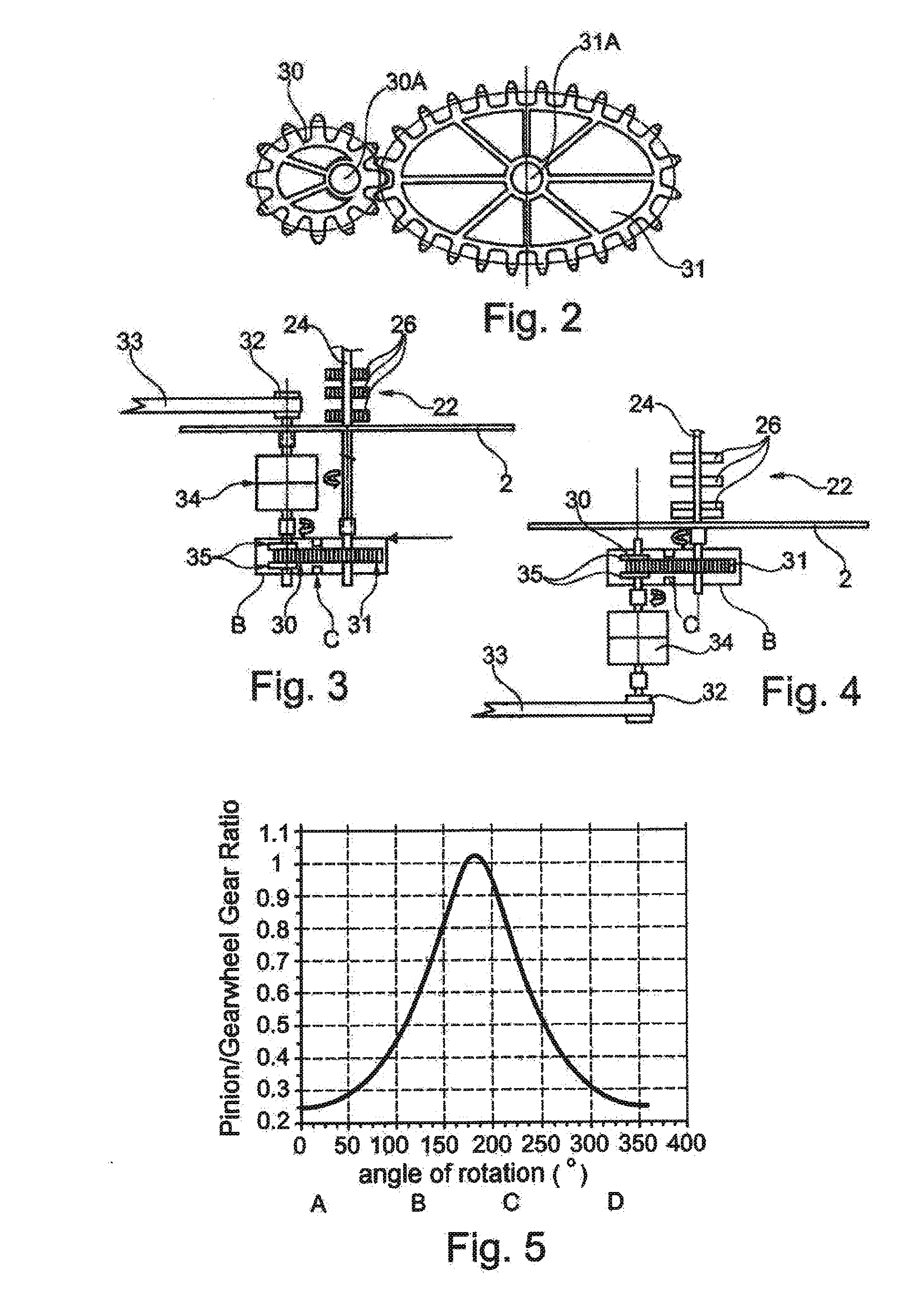
[0039]FIG. 1 shows, merely by way of example, a stacker device for stacking flat postal articles and having an electromechanical actuator of the bucket wheel type.

[0040]Firstly, the stacker device includes a stationary frame, designated by reference 2. It also has an inlet corridor 4, via which the flat postal articles arrive. In this example, the mailpieces are, more particularly, envelopes or letters of small and / or large format.

[0041]Typically, this inlet is put into communication with a conveyor device (not shown) that is part of a conventional-type postal sorting machine.

[0042]This stacker device also defines a zone 6 for receiving and storing the articles, which zone lies laterally between a jogging edge 8, against which the flat articles bear, and a retaining edge 10. In addition, the longitudinal direction of the device, in which direction the stack of flat articles moves as it is being formed, is referenced D.

[0043]A plate 12 forming a sliding edge makes it possible to guid...


PUM

PropertyMeasurementUnit
radiusaaaaaaaaaa
angle θfaaaaaaaaaa
speedaaaaaaaaaa

Abstract

A mail stacker unit in a postal sorting machine includes a stacking actuator (22) driven in stop-start rotation for the purpose of stacking mailpieces on edge in a storage receptacle. The actuator is coupled in rotation to a clutch brake (34) driven at constant speed, and elliptical gearing (30, 31) is also provided between the clutch brake and said stacking actuator.

Description

TECHNICAL FIELD[0001]The invention relates to a stacker unit including a stacking actuator driven in stop-start rotation for the purpose of stacking flat articles on edge in a storage receptacle.[0002]The invention applies more particularly to stacking flat mailpieces but it is also applicable to stacking other flat articles such as banknotes, for example.[0003]A postal sorting machine may have a large number of sorting outlets. For example, in postal sorting machines for small envelopes, each sorting outlet can be constituted by a stacker as indicated above.[0004]The storage receptacle of the stacker can contain a large number of envelopes, and up to about twenty kilograms of mail in a stack and on edge. Such a stacker is suitable for stacking, at the head of the stack, a new mailpiece that is brought by an on-edge conveyor to the sorting outlet in question. Generally, the on-edge conveyor is a conveyor having nipping belts.PRIOR ART[0005]Such a stacker for a postal sorting machine...

Claims


Application Information

Patent Timeline
Patent Type & Authority Applications(United States)
IPC IPC(8): F16H35/02B65H31/06B65H29/60B07C3/00B65H29/40
CPCF16H35/02B07C3/008B65H29/40F16H2035/003B65H31/06F16H2035/001B65H29/60B65H2301/321B65H2403/42B65H2403/72B65H2403/725B65H2511/212B65H2511/514B65H2513/51B65H2553/22B65H2553/23B65H2553/40B65H2701/1313B65H2701/1916B65H2220/03B65H2220/01B65H2220/11B65H2220/02
Inventor BEAUGRAND, WILFRID
Owner SOLYSTIC
Why Eureka
Try Eureka