Drive support system and drive support method

a technology of support system and support method, applied in surveying and navigation, navigation instruments, instruments, etc., can solve the problems of annoying the driver, and affecting the driving experien

Active Publication Date: 2016-09-29
MITSUBISHI ELECTRIC CORP
View PDF5 Cites 4 Cited by
  • Summary
  • Abstract
  • Description
  • Claims
  • Application Information

AI Technical Summary

Benefits of technology

[0017]According to the present invention, it offers an advantage of being able to give the drive support with appropriate contents at appropriate timing for the driver.

Problems solved by technology

Thus, according to the conventional techniques, they are likely to distract attention from driving because the display contents of the onboard equipment are not switched to a camera image without a particular operation different from the driving operation (such as a touch operation).
In addition, when switching to the display contents of the onboard equipment in accordance with the speed of the vehicle, even if the driver does not want to refer to a camera image, the display contents are switched, which is annoying to the driver.

Method used


Image

  • Drive support system and drive support method
  • Drive support system and drive support method
  • Drive support system and drive support method

Examples


embodiment 1

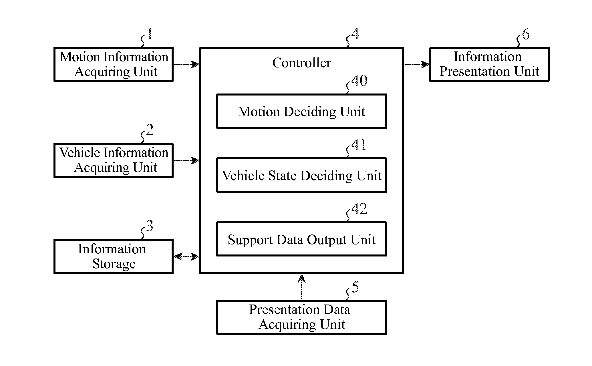
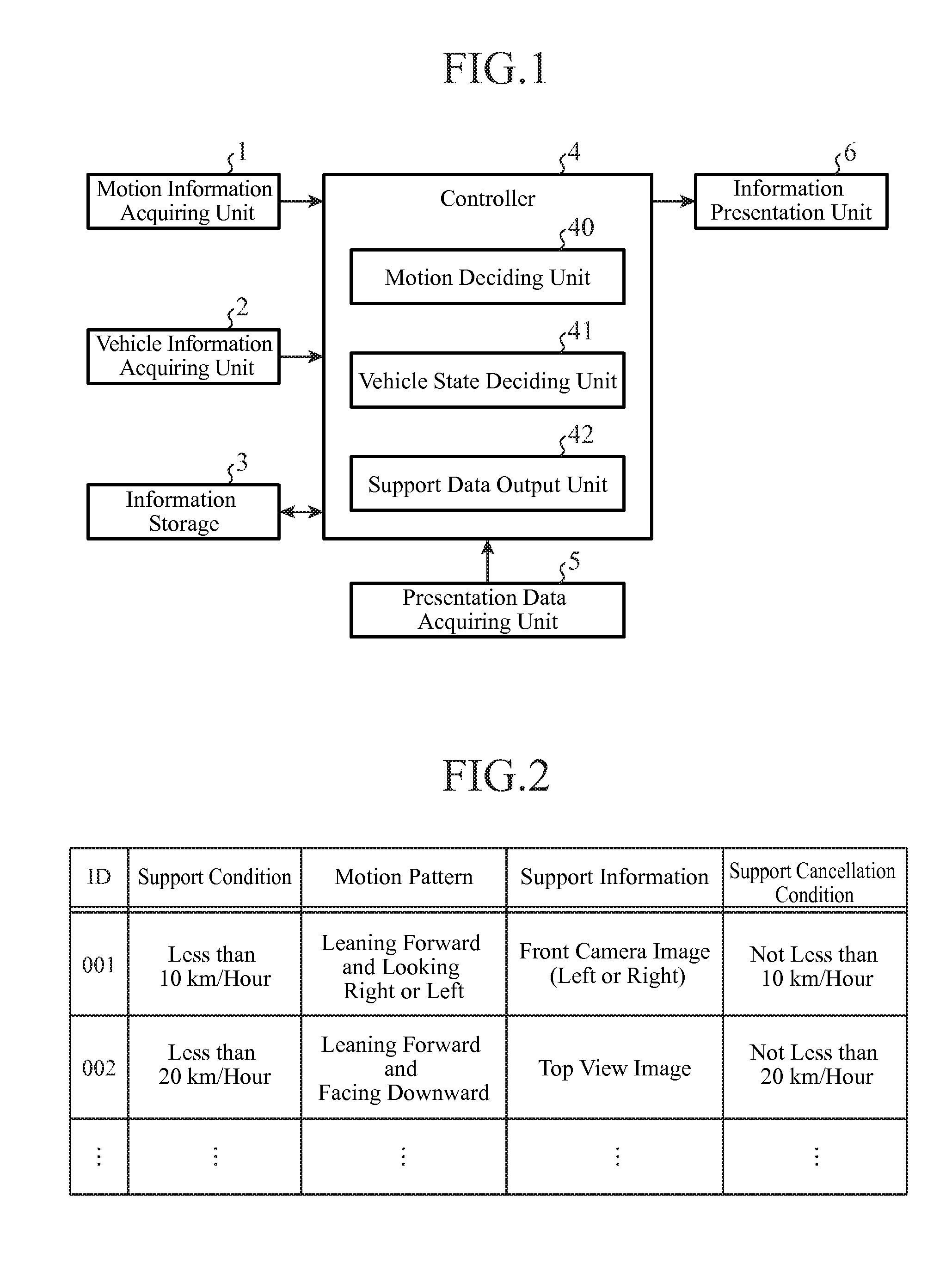
[0031]FIG. 1 is a block diagram showing a configuration of a drive support system of an embodiment 1 in accordance with the present invention. In addition, FIG. 2 is a table showing an example of support condition data in the embodiment 1.

[0032]The drive support system shown in FIG. 1, which is a system mounted on a vehicle to give drive support to a driver, comprises a motion information acquiring unit 1, a vehicle information acquiring unit 2, an information storage 3, a controller 4, a presentation data acquiring unit 5 and an information presentation unit 6.

[0033]The motion information acquiring unit 1 is an information acquiring unit that acquires motion information of a driver of a vehicle. For example, it acquires information such as an image of the driver taken with an in-vehicle camera, which will enable the system to recognize driver's motion.

[0034]The vehicle information acquiring unit 2 is an information acquiring unit that acquires vehicle information about a state of t...

embodiment 2

[0094]FIG. 4 is a block diagram showing a configuration of a drive support system of an embodiment 2 in accordance with the present invention. The drive support system shown in FIG. 4 comprises a positional information acquiring unit 7 in addition to the configuration of the embodiment 1. Furthermore, instead of the controller 4, it has a controller 4A that comprises a history information management unit 43 added to the functional components of the controller 4.

[0095]The positional information acquiring unit 7 is an information acquiring unit that acquires the positional information of the vehicle. For example, it analyzes GPS signals received from GPS (Global Positioning System) satellites to acquire the positional information of the vehicle. Alternatively, it can acquire the positional information using the output of a gyroscope and vehicle speed pulses of a vehicle speed sensor.

[0096]The history information management unit 43 stores the place where the drive support was given and...

embodiment 3

[0126]FIG. 6 is a block diagram showing a configuration of a drive support system of an embodiment 3 in accordance with the present invention. The drive support system shown in FIG. 6, which has basically the same configuration as the embodiment 2, comprises instead of the information storage 3 an information storage 3A including a map DB (database) 30 in addition to the stored contents shown in the embodiments 1 and 2, and further comprises instead of the controller 4A a controller 4B including a map information deciding unit 44 as an additional functional component.

[0127]The map DB 30 is a database that records map information including facility information (such as latitude and longitude of a facility, its classification and parking lot information) and road information (such as road data specifying the width of a road and an intersection). Although FIG. 6 shows an example which stores the map DB 30 in the information storage 3A, it can be downloaded from an external map data ser...


PUM


Abstract

A drive support system includes a motion information acquiring unit 1 that acquires motion information of a driver of a vehicle; a vehicle information acquiring unit 2 that acquires vehicle information about a state of the vehicle; a controller 4 that decides drive support contents corresponding to the motion pattern matching the motion information of the driver and to the state of the vehicle the vehicle information indicates from the support condition data that records drive support contents corresponding to a motion pattern of a driver to be provided with the drive support and the state of the vehicle; and an information presentation unit 6 that presents the drive support contents the controller 4 decides.

Description

TECHNICAL FIELD[0001]The present invention relates to a drive support system and a drive support method that give appropriate drive support in response to a motion of a driver.BACKGROUND ART[0002]Conventionally, techniques have been proposed which support driving by switching display contents of onboard equipment to an image of a driver's blind spot taken with an on-vehicle camera (front camera, for example) in response to a user operation (pushing down of a button, for example).[0003]In addition, there is a technique that supports the driving when the driver's vehicle travels within a prescribed speed by switching to a camera image outside the vehicle taken with an on-vehicle camera.[0004]Thus, according to the conventional techniques, they are likely to distract attention from driving because the display contents of the onboard equipment are not switched to a camera image without a particular operation different from the driving operation (such as a touch operation).[0005]In addit...

Claims


Application Information

Patent Timeline
Patent Type & Authority Applications(United States)
IPC IPC(8): G01C21/36
CPCG01C21/3667B60R1/00B60R2300/205B60R2300/70B60R11/02B60K35/00B60K2370/152B60K2370/186B60K2370/21B60K2370/1868B60K2370/193B60K2370/176B60K2370/171
Inventor KUMAGAI, TARO
Owner MITSUBISHI ELECTRIC CORP
Why Eureka
Try Eureka