

Failure rate calculation device
- Summary
- Abstract
- Description
- Claims
- Application Information
AI Technical Summary
Benefits of technology
Problems solved by technology
Method used
Image

Examples
example
[Wiring Example]
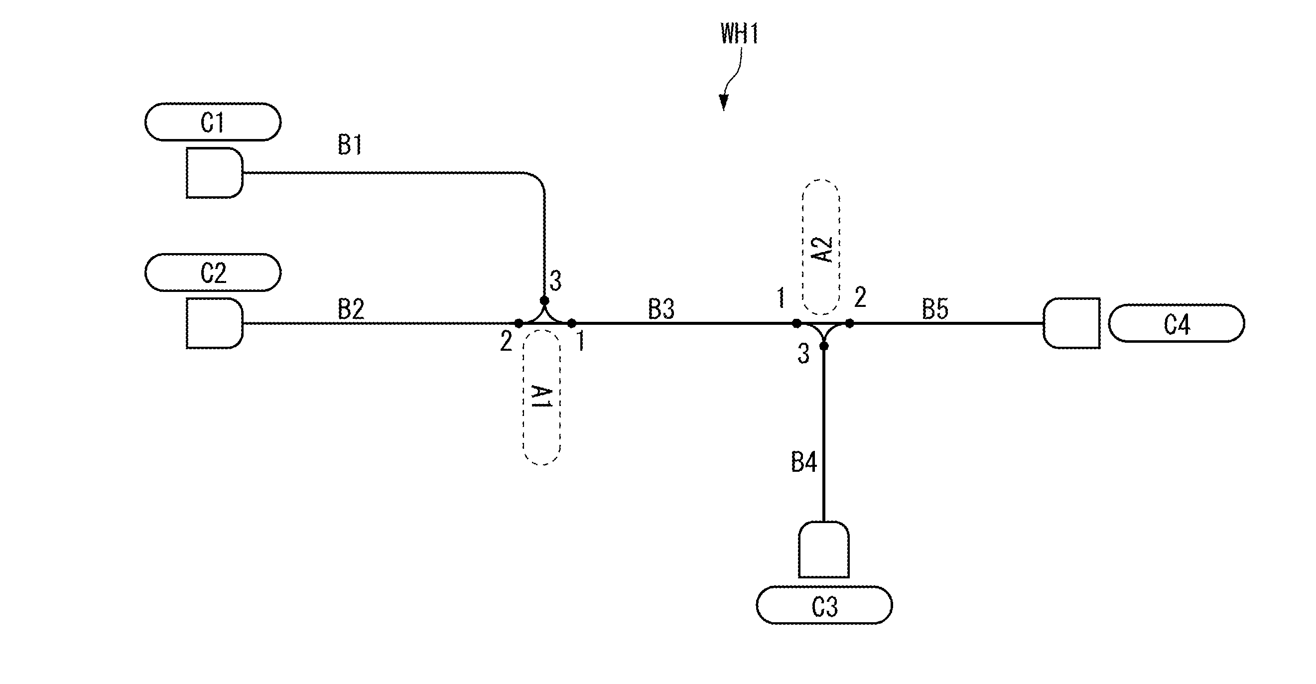
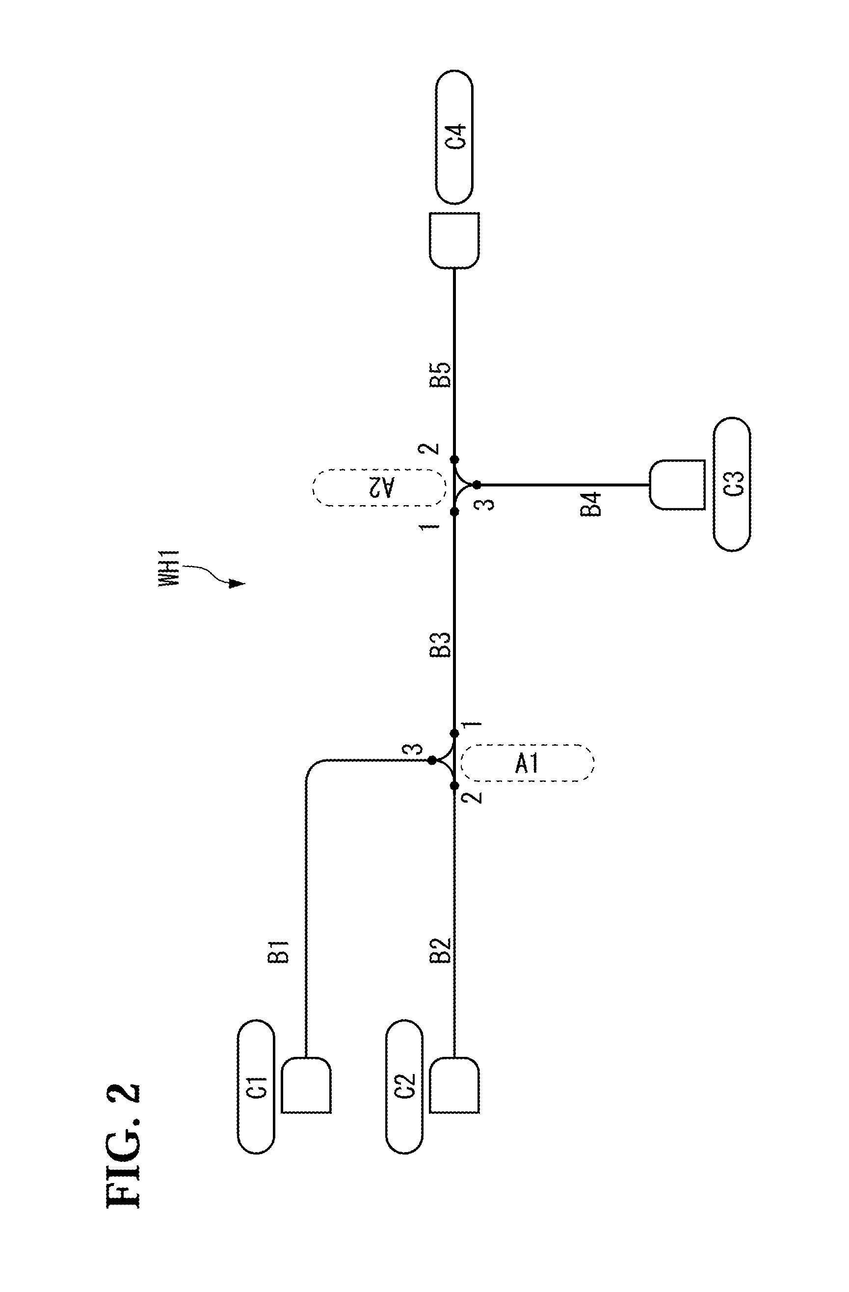
[0042]FIG. 2 shows one example of a harness of which the failure rate is calculated in this embodiment. This wiring example corresponds with the above-mentioned wire harness diagram (WHD). Here, the numbers of the connectors and the bundles, which are components of the wiring example, are minimized for easy understanding, but this embodiment can be applied to a larger wiring system as well.
[0043]In a harness WH1 of FIG. 2, four connectors, a connector C1, a connector C2, a connector C3, and a connector C4, are interconnected via a bundle B1, a bundle B2, a bundle B3, a bundle B4, and a bundle B5, as well as via a relay point A1 and a relay point A2. While only the connectors are shown at all the terminal ends here, these connectors C1 to C4 are usually attached to devices such as an input device, a control device, and an output device, or attached to relay connectors which interconnect a plurality of harnesses. The relay points A1 to A2 are identification information...
PUM
 Abstract
Description
Claims
Application Information