
Image processing device, camera device and image processing method

a technology of image processing and camera, applied in the field of image processing apparatus, camera apparatus, image processing method, can solve the problems of long time required for a work, difficult to find the change in details of the subject, and difficult to confirm the contents of the work, so as to facilitate the contents of the change part, easy to confirm the contents of the image, and easy to confirm whether or not the subject is changing.

Active Publication Date: 2012-03-20
OPTEX CO LTD
View PDF4 Cites 0 Cited by
  • Summary
  • Abstract
  • Description
  • Claims
  • Application Information

AI Technical Summary

Benefits of technology

The present invention relates to an image processing apparatus for continuously photographing a subject and generating an image therefrom. The apparatus includes a moving part detecting unit for detecting moving parts of the image caused by changes in the subject, a moving area image cutting-out unit for cutting out the area corresponding to the moving part, and a corrected / enlarged image generating unit for generating a corrected / enlarged image by subjecting the moving area image or the changing area image to a correction processing and an enlargement processing. The apparatus can detect and watch the moving parts of the image, making it easy to confirm the contents of the image. Additionally, the apparatus can cut out the changing parts of the image and prevent them from being displayed in different places with an overlap. The technical effects of the invention include improved image processing accuracy and improved user experience.

Problems solved by technology

This raises a problem that a long time is required for a work of confirming whether or not there is an abnormality, namely, a change within a monitored range.
This raises a problem that a change in details of the subject is hard to find, and that contents thereof are also hard to confirm.

Method used


Image

  • Image processing device, camera device and image processing method
  • Image processing device, camera device and image processing method
  • Image processing device, camera device and image processing method

Examples


first embodiment

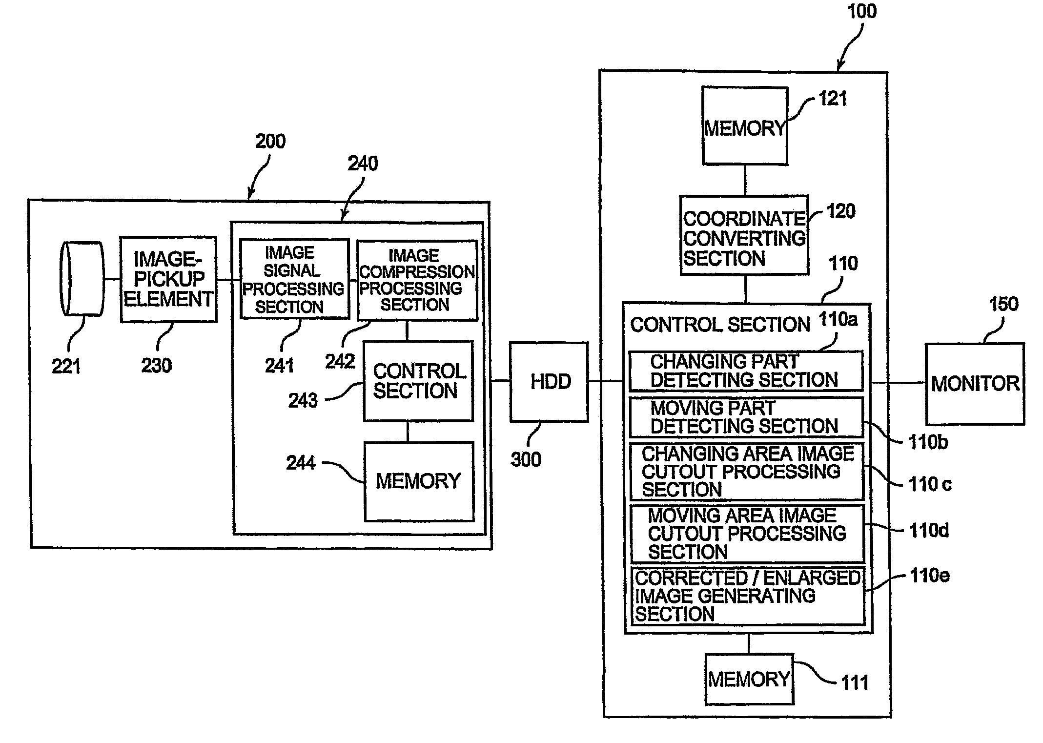
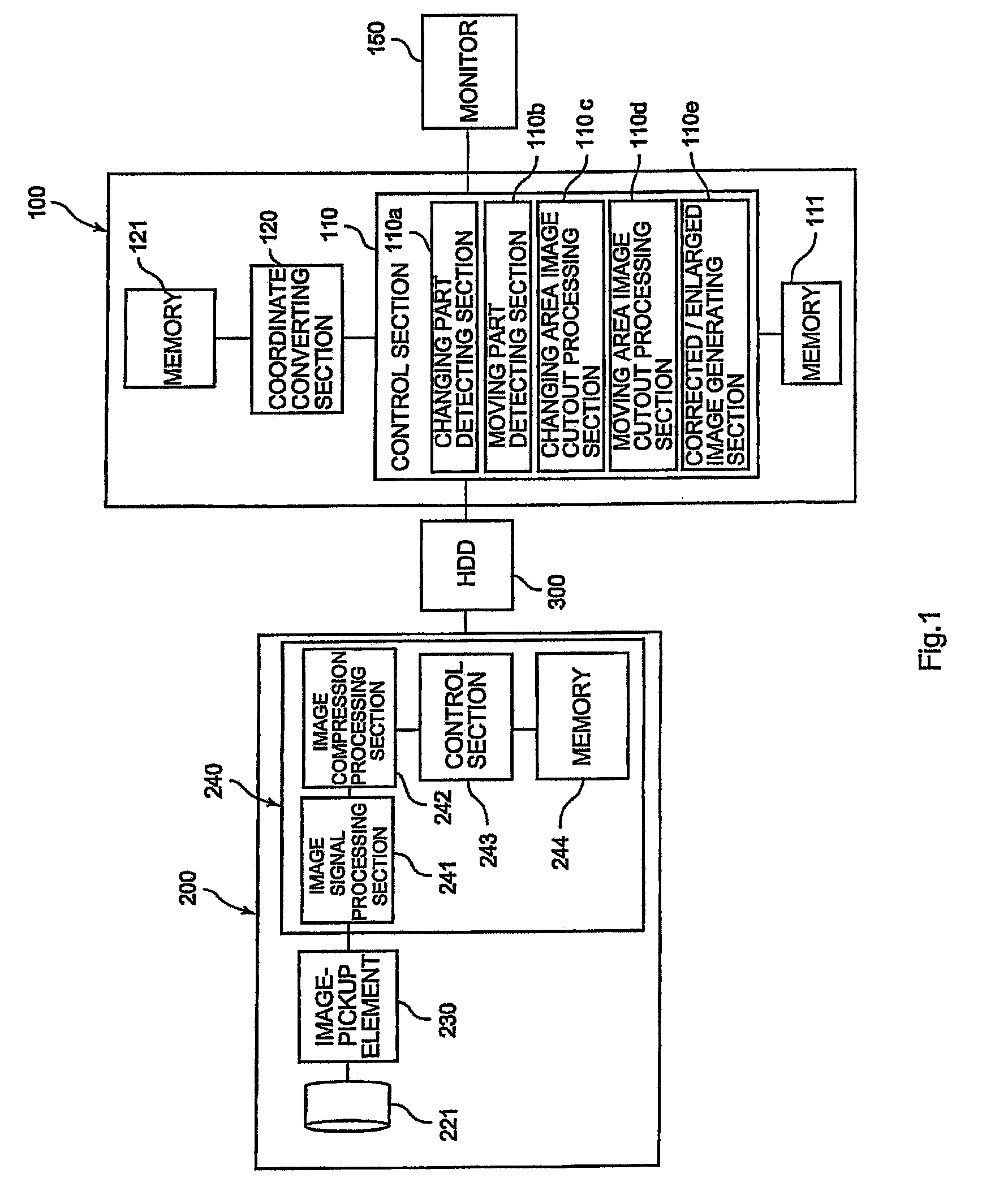
[0062]Description is made of an image processing apparatus 100 according to a first embodiment of the present invention by referring to FIGS. 1 to 7(G). Note that an image processing method is described along with an operation of the image processing apparatus 100.

[0063]As illustrated in FIG. 1, a case is shown in which the image processing apparatus 100 is used when an image obtained by photographing is read from a hard disk drive (hereinafter, referred to as “HDD”) 300 serving as recording unit in which an image obtained by photographing by a camera section 200 is recorded, and is displayed on a monitor 150.

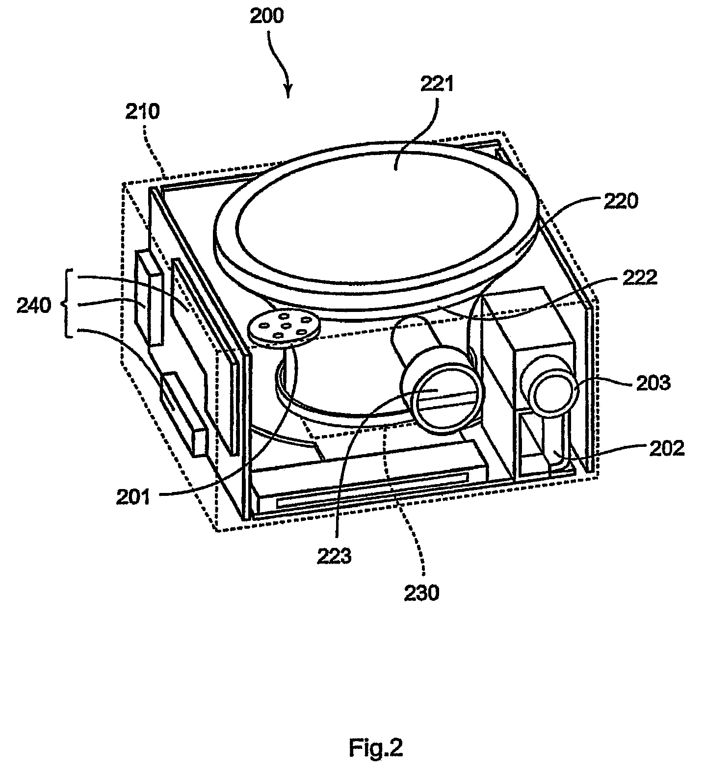
[0064]First, FIG. 2 is referenced to describe a structure of the camera section 200. The camera section 200 includes an external casing 210 illustrated by the dotted lines of FIG. 2, an optical system 220, an image-pickup element 230 serving as image-pickup unit, and a circuit device 240. The external casing 210 has a small shape exhibiting substantially a flat rectangular para...

second embodiment

[0163]In the above-mentioned first embodiment, a photographic frame rate is set as a relatively high photographic frame rate, for example, 16 frames / sec or 30 frames / sec, and the images obtained by photographing are reproduced as a moving image by being continuously reproduced in an order of the photographic frames. In contrast, the photographing may be performed by making photographic frame rate as small as, for example, 1 frame / sec.

[0164]In the case where the photographing is performed at the small photographic frame rate, the detection of the moving part no longer has a significant purpose, and the detection of the changing part may often becomes a main purpose. For example, the photographic frame rate may be made small for the purpose of monitoring whether or not there is a suspicious object. In the case where the detection of the moving part is not performed, the image processing apparatus 100 may perform an image processing shown by a flowchart illustrated in FIG. 8 without in...

modified example

[0171]In each of the above-mentioned embodiments, instead of displaying the changing part or the moving part onto the monitor 150, from among all of the photographic frames, the photographic frames including the changing part or the moving part may be gathered in another file as a changing part file or a moving part file, and recorded onto the HDD 300. According to this arrangement, if image data of the changing part / moving part file is reproduced, only the changing part or the moving part can be reproduced and watched. Note that not only the changing part / moving part file but also all of the photographic frames of the entire range picture may be recorded onto the HDD 300.

[0172]Note that a frame number assigned to the photographic frame including the changing part or the moving part and a chapter number of a chapter including the frame may be recorded. According to this arrangement, only the changing part or the moving part can be reproduced and watched based on the frame number or ...


PUM


Abstract

Provided are an image processing apparatus and method in which, when there is a change in a subject, a picture in which a changing part thereof is enlarged makes it possible to easily confirm whether or not the subject is changing and contents of the changing part. The image processing apparatus (100) for performing an image processing on images obtained by continuously photographing a subject and by imaging light therefrom on image-pickup means (230) through a photographic lens (221) includes: moving part detecting means (110b) for detecting a moving part of the image obtained by the photographing, the moving part having occurred due to a change in the subject; moving area image cutting-out means (110d) for cutting out, as a moving area image, an area including the image obtained by the photographing corresponding to the moving part in which a move has been detected by the moving part detecting means (110b); and corrected / enlarged image generating means (110e) for generating a corrected / enlarged image by subjecting the moving area image to a correction processing for a distortion due to the photographic lens and to an enlargement processing.

Description

CROSS REFERENCE TO RELATED APPLICATIONS[0001]This is a U.S. national stage of application No. PCT / JP2007 / 059838, filed on 14 May 2007. Priority under 35 U.S.C. §119(a) and 35 U.S.C. §365(b) is claimed from Japanese Application No. 2006-136146, filed 16 May 2006, the disclosure of which is also incorporated herein by reference.TECHNICAL FIELD[0002]The present invention relates to an image processing apparatus, a camera apparatus, and an image processing method.BACKGROUND ART[0003]JP2004-271902A discloses an example of a monitor camera apparatus including an image processing apparatus for performing an image processing on an image obtained during photographing by imaging light on an image-pickup element such as a charge coupled device (CCD) or complementary metal oxide semiconductor (CMOS) sensor. The monitor camera apparatus is configured to record a picture obtained by the photographing onto a video cassette recorder.[0004]Patent Document 1: JP2004-271902A (refer to description in A...

Claims


Application Information

Patent Timeline
Patent Type & Authority Patents(United States)
IPC IPC(8): H04N5/232G06T3/00G06T3/40H04N7/18
CPCG06T3/00G06T3/40G06T7/2053G08B13/19602H04N7/183G06T2207/10016G06T7/254H04N7/18H04N23/00
Inventor OGAWA, TATSURO
Owner OPTEX CO LTD
Learn More