Camera system

Active Publication Date: 2021-03-04
CIAO
View PDF0 Cites 0 Cited by
  • Summary
  • Abstract
  • Description
  • Claims
  • Application Information

AI Technical Summary

Benefits of technology

[0019](1) A first aspect of the present invention provides a camera system, comprising: a weather information-acquiring unit acquiring weather information provided with respect to weather, the weather information including information relating to an area of interest; a plurality of cameras installed within a plurality of bases, respectively; a camera installation information-storing unit storing information with respect to positions of the bases wherein the plurality of cameras are installed; an image data-storing unit storing images photographed by the plurality of cameras respectively as moving images; a camera-specifying unit using the weather information acquired by the weather information-acquiring unit to specify a camera installed within the area of interest based on the information with respect to the positions of the bases, the information with respect to the positions of the bases being stored in the camera installation information-storing unit; and a moving image-providing unit acquiring from the image data-storing unit moving images of the camera specified by the camera-specifying unit to provide the acquired moving images.
[0020]According to this arrangement, moving images of a camera installed wi

Problems solved by technology

Whereas, when a lot of cameras have been installed within a plurality of bases, management of the plurality of cameras may become difficult.
That is, as increase in the installation of many cameras to various places throughout the country, it becomes difficult to specify a specific camera among a lot of

Method used


Image

  • Camera system
  • Camera system
  • Camera system

Examples


Embodiment Construction

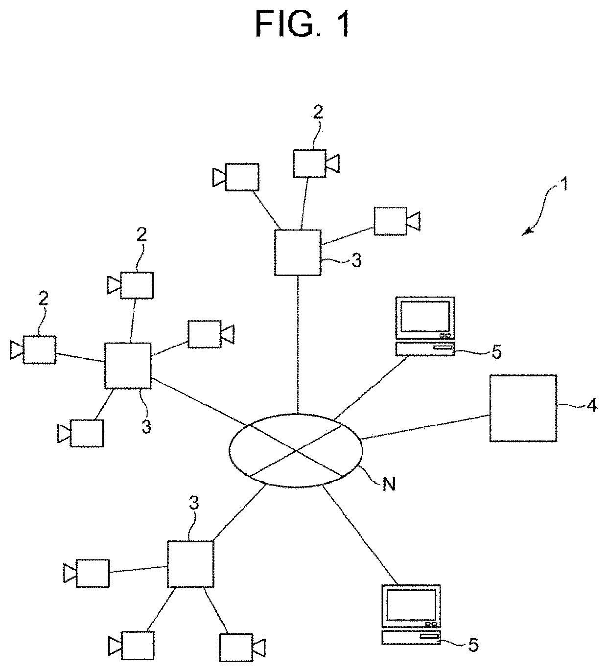
[0060]FIG. 1 shows a schematic structure of a camera system in Embodiment 1 according to the present invention, and FIG. 2 is a block diagram of the camera system in FIG. 1.

[0061]As shown in FIG. 1, a camera system 1 in Embodiment 1 according to the present invention includes the following elements:

[0062]a plurality of cameras 2 being installed within a plurality of bases, respectively;

[0063]a base server 3 being installed within the respective base, and the plurality of cameras 2 being connected to the base server 3, respectively; and

[0064]a cloud server 4 being connected to the base server 3 via an electric telecommunication line N.

[0065]The plurality of cameras 2 are imaging devices photographing still images at predetermined time intervals (for example, time intervals of 1 / 120 through 1 [sec]) to obtain continuous frame images.

[0066]The number of the plurality of cameras 2 installed within each base may be one, two, or more.

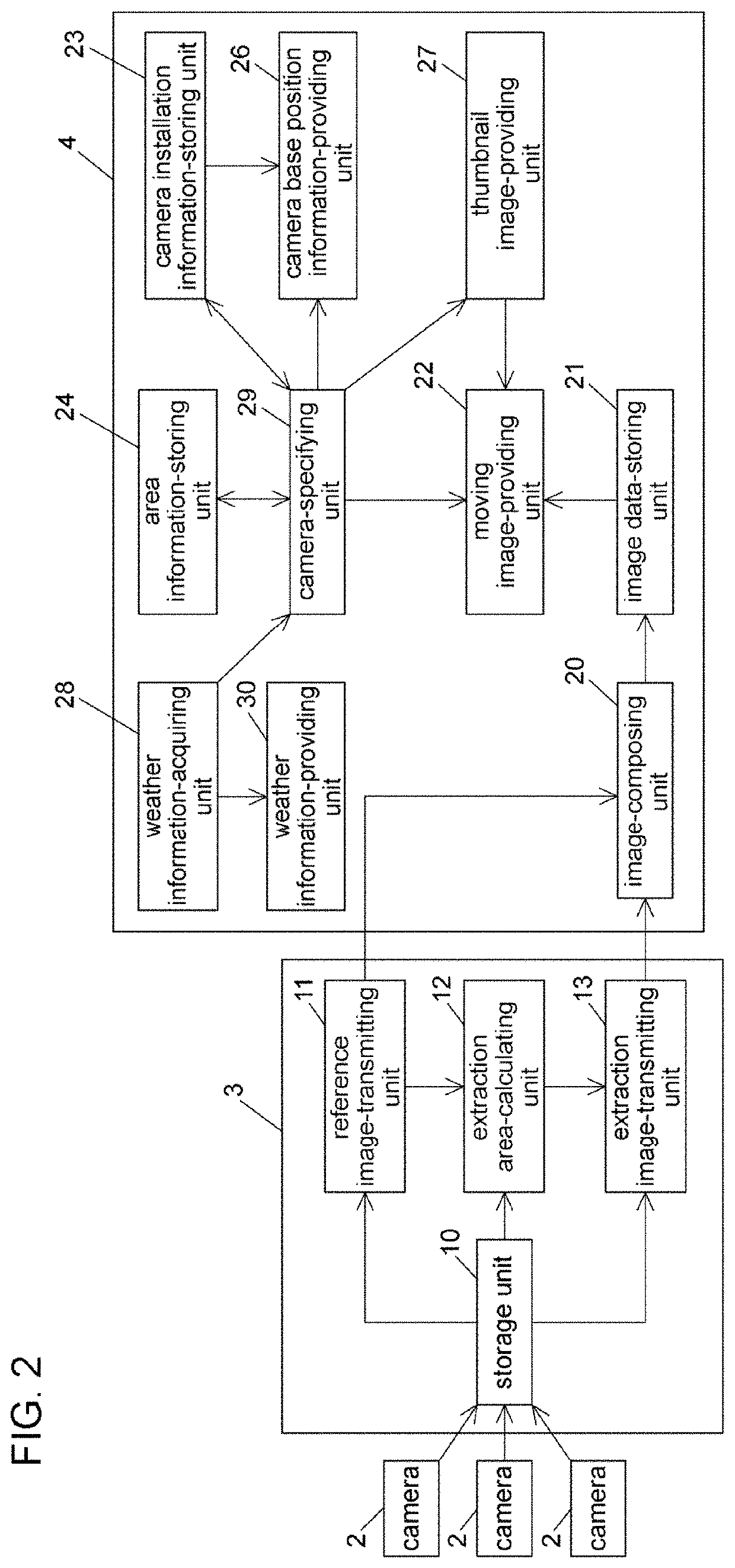
[0067]As shown in FIG. 2, the base server 3 includes th...


PUM


Abstract

Provided is a camera system that includes: a weather information-acquiring unit acquiring weather information provided with respect to weather, the weather information including information relating to an area of interest; a plurality of cameras installed within a plurality of bases, respectively; a camera installation information-storing unit storing information with respect to positions of the bases wherein the plurality of cameras are installed; an image data-storing unit storing images photographed by the plurality of cameras respectively as moving images; a camera-specifying unit using the weather information acquired by the weather information-acquiring unit to specify a camera installed within the area of interest based on the information with respect to the positions of the bases, the information with respect to the positions of the bases being stored in the camera installation information-storing unit; and a moving image-providing unit acquiring from the image data-storing unit moving images of the camera specified by the camera-specifying unit to provide the acquired moving images.

Description

1. FIELD OF THE INVENTION[0001]The present invention relates to a camera system that displays images photographed by a plurality of cameras installed within a number of bases, more particularly, to a camera system that can display the camera images in accordance with weather information.2. DESCRIPTION OF THE RELATED ART[0002]The applicant has already developed an image-transmitting apparatus capable of suppressing a data transmission amount while avoiding blur and / or an after-image upon transmitting continuous frame images to compose moving images (See, Reference 1: Japanese Registered Patent No. 6049024.).[0003]This image-transmitting apparatus enables to obtain moving images with high quality in the small data transmission amount, and to install a lot of cameras within a plurality of bases at low cost. Further advances are expected toward spreading of cameras for the purpose of crime prevention, monitoring, and so on.[0004]Reference 1: Japanese Registered Patent No. 6049024OBJECTS...

Claims


Application Information

Patent Timeline
IPC IPC(8): H04N7/18H04N5/77G09B29/10G09B29/00G01W1/00
CPCH04N7/181H04N5/77G06F3/0482G09B29/007G01W1/00G09B29/106G08B25/00G09B29/00G09B29/10H04N7/18H04N21/2743H04N21/432
Inventor WATAHIKI, RYUICHINITTA, TOMOAKI
Owner CIAO
Why Eureka
Try Eureka