Gas separation system and enriched gas production method

a gas separation system and gas production method technology, applied in the field of gas separation systems, can solve the problems of increasing the amount of gas flowing in the system, low permeability, and low recoverability rate, and achieve the effect of reducing the number of membrane modules, reducing the requisite compression power, and high pressur

Active Publication Date: 2016-10-06
UBE CORP
View PDF28 Cites 8 Cited by
  • Summary
  • Abstract
  • Description
  • Claims
  • Application Information

AI Technical Summary

Benefits of technology

[0054]According to the invention, a total required membrane area of the entire system, for example, the number of membrane modules can be reduced. With respect to the recirculation system, because the retentate gas discharged from the third gas separation membrane unit has a relatively high pressure, the invention makes it feasible to reduce the requisite compression power of the entire system by returning the retentate gas from the third unit to the first retentate gas line of the first gas separation membrane unit, which line has a relatively high pressure resulting from the passage through the first compression means, or by joining the retentate gas from the third unit to the retentate gas discharge line of the second gas separation membrane unit. In particular, the invention provides the advantage that the operating conditions of the first and second compression means are not so limited. This broadens the choice of the compression means and expands the flexibility of system design. In a preferred embodiment of the invention, the system is designed such that the permeability of the second gas separation membrane unit 12 is higher than that of the third gas separation membrane unit 13 in operation and that the gas selectivity of the third gas separation membrane unit 13 is higher than that of the second gas separation membrane unit 12 in operation. This design permits further reduction of the membrane area, e.g., further reduction of the number of membrane modules, of the second gas separation membrane unit while maintaining a high gas recovery rate.

Problems solved by technology

In that case, however, seeing that the permeability is low, it is necessary to increase the membrane area or increase the operating pressure.
Although a membrane having a high-permeability, on the other hand, does not require an increase in membrane area or an increase in operating pressure, the achievable recovery rate is low because of the low gas selectivity.
When a membrane having a high gas permeability is used, the amount of the gas flowing in the system increases due to the low gas selectivity.

Method used


Image

  • Gas separation system and enriched gas production method
  • Gas separation system and enriched gas production method
  • Gas separation system and enriched gas production method

Examples


examples

[0099]The present invention will now be illustrated in greater detail by way of Examples, but understandably, the scope of the present invention is not limited to these Examples.

examples 1 to 8

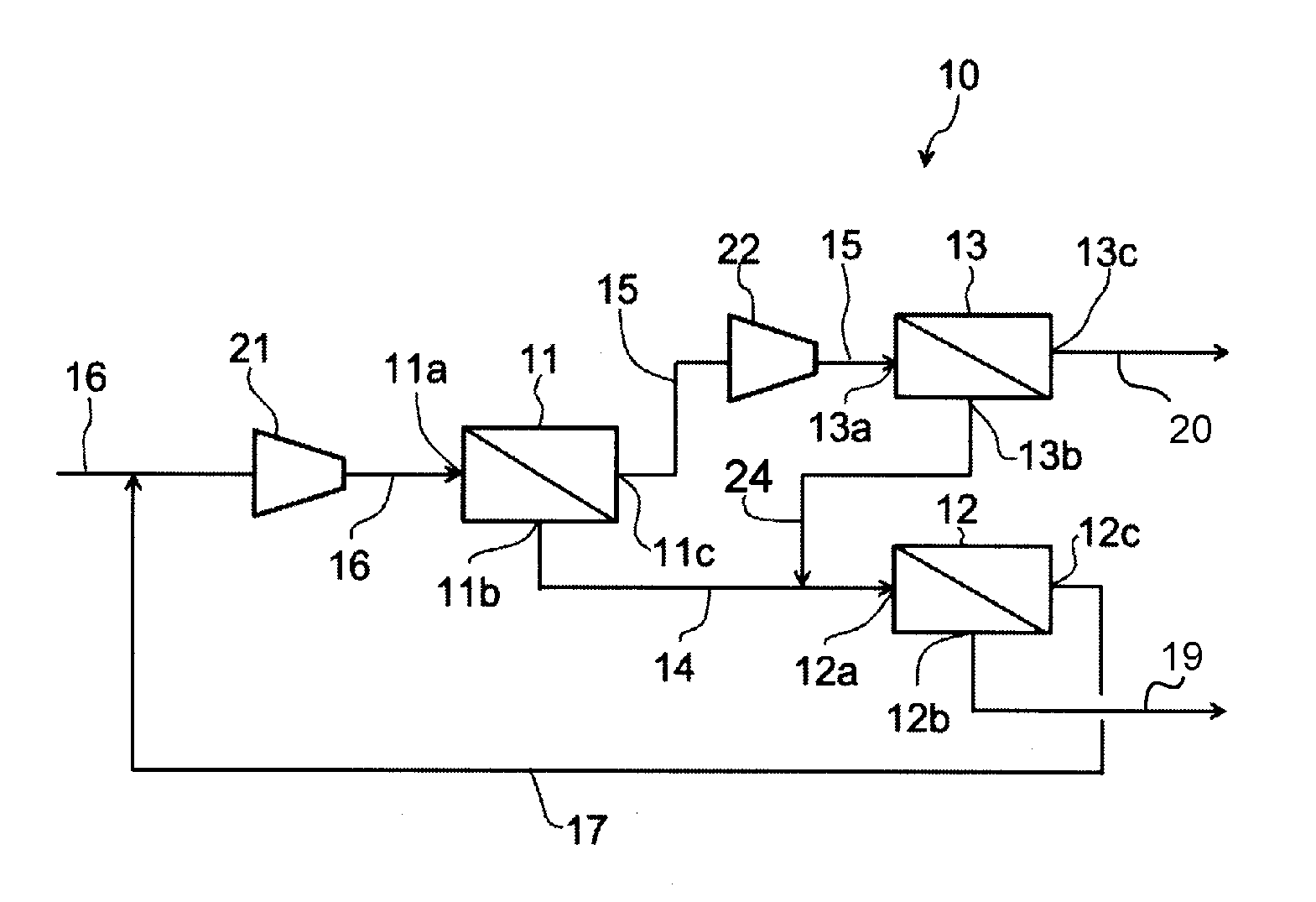
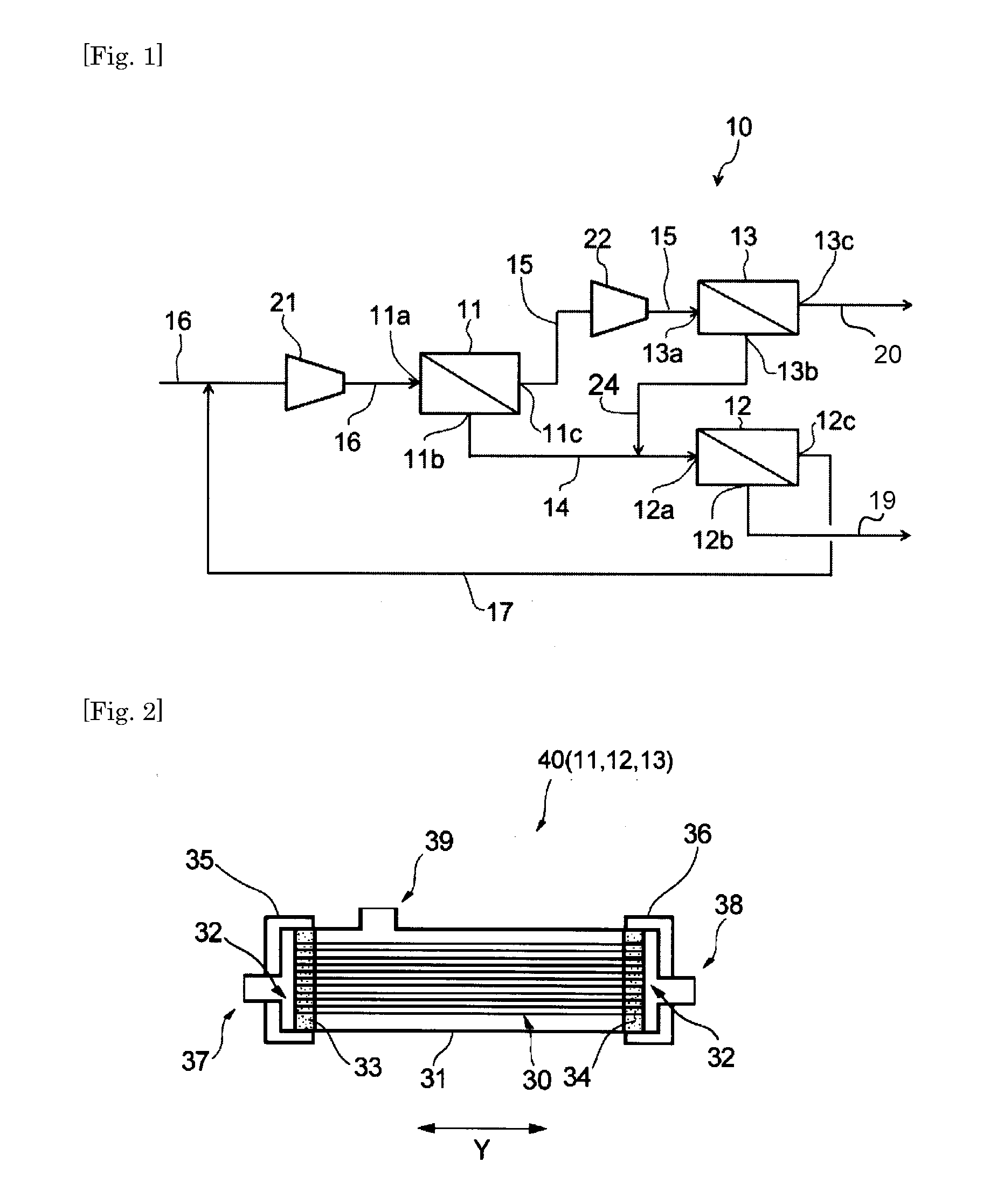
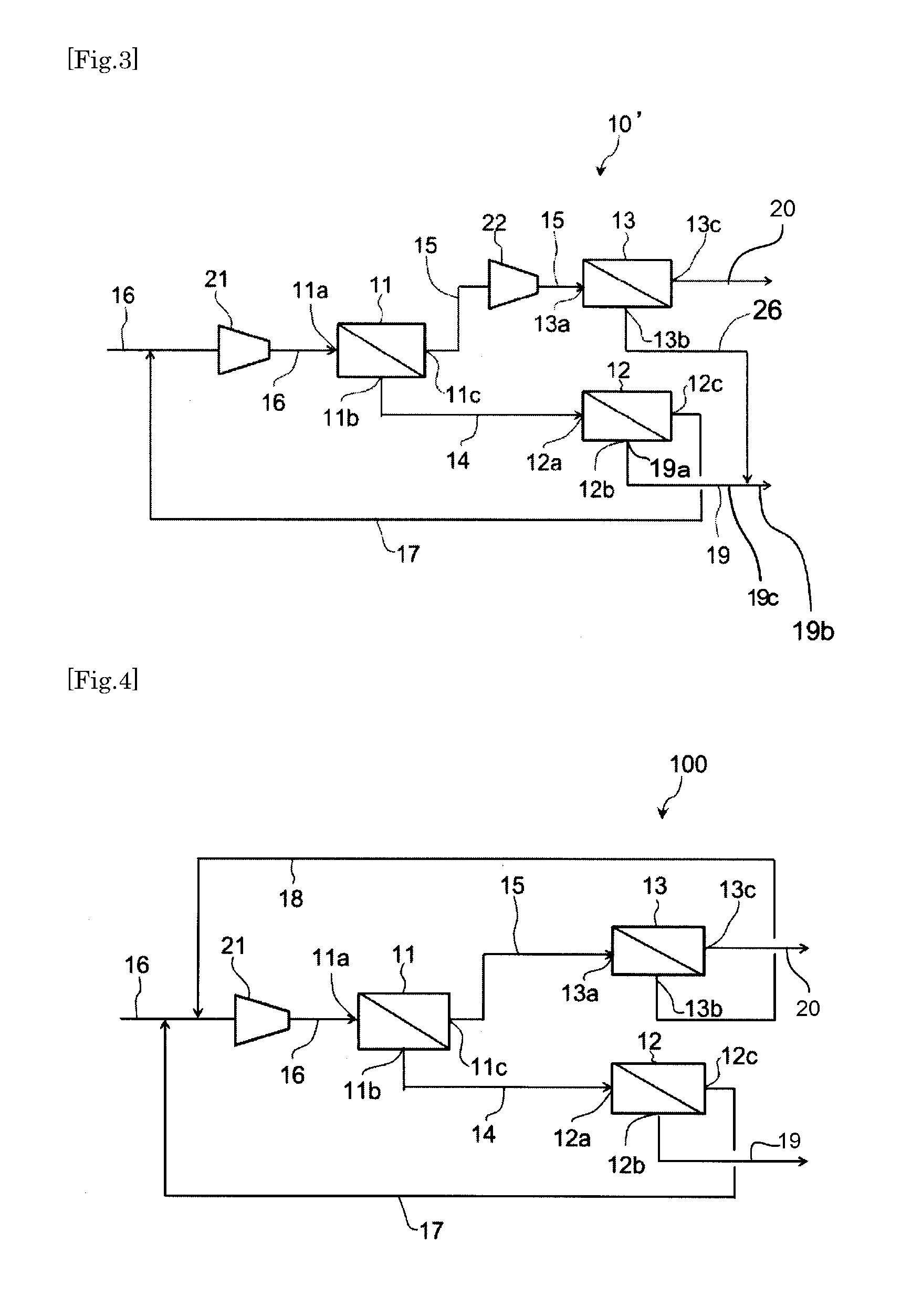
[0100]A gas mixture containing carbon dioxide and methane was separated using the gas separation system 10 shown in FIG. 1 or the gas separation system 10′ shown in FIG. 3. Compressors were used as the first and second compression means 21, 22 in the systems 10, 10′. The pressure, flow rate, and composition of the gas mixture were as shown in Table 1 below. The first to third gas separation membrane units 11, 12, 13 were each made by connecting, in parallel, a plurality of gas separation membrane modules shown in Table 1 (gas separation membrane module A or B). Gas separation membrane modules A and B each have polyimide hollow-fiber membranes housed in a casing, and are different in composition of the polyimide hollow fiber membranes. Table 2 below shows P′CO2, P′CH4, and P′CO2 / P′CH4 of the gas separation membrane modules A and B, each measured at an operating temperature of 50° C. In Table 2, P′CO2, P′CH4, and P′CO2 / P′CH4 of the gas separation membrane module A′ are values of the g...


PUM


Abstract

A gas separation system includes: first, second, and third gas separation membrane units. A first retentate gas line connects a retentate gas discharge port of the first unit and gas inlet port of the second unit. A first permeate gas line connects a permeate gas discharge port of the first unit and gas inlet port of the third unit. A feed gas mixture supply line is connected to a gas inlet port of the first unit, and provided with first compression elements. The first permeate gas line is provided with second compression elements. The permeate gas discharge port of the second unit is connected by a second permeate gas line to the suction side of the first compression elements in the feed gas mixture supply line. A retentate gas discharge port of the third unit is connected by a third retentate gas line to the first retentate gas line.

Description

TECHNICAL FIELD[0001]The present invention relates to a gas separation system for separating a gas mixture using a plurality of gas separation membrane units and an enriched gas production method using the gas separation system.BACKGROUND ART[0002]A membrane separation technique, which makes use of the difference in permeability of membranes to different gases, is known for separating a gas mixture containing at least two different gas species into the individual gas species. According to this method, the permeate gas or the retentate gas can be recovered to give a target gas either as a high purity, high-permeability gas or a high purity, low-permeability gas.[0003]The permeability of a membrane, which is the volume of permeation, through the membrane, of each gas contained in the gas mixture per unit membrane area, per unit time, and per unit partial pressure difference, can be expressed as P′ (unit: ×10−5 cm3(STP) / cm2·sec·cmHg). The gas selectivity of a membrane can be expressed ...

Claims


Application Information

Patent Timeline
Patent Type & Authority Applications(United States)
IPC IPC(8): B01D53/22B01D63/04
CPCB01D53/226B01D63/046B01D2317/027B01D2313/24B01D2053/221B01D53/225B01D2256/245B01D2257/504B01D53/22B01D53/227B01D63/02B01D2258/05Y02C20/40
Inventor FUKUDA, NOBUHIKONAKAMURA, TOMOHIDE
Owner UBE CORP
Why Eureka
Try Eureka