
Vehicle seat air-conditioning device

Inactive Publication Date: 2016-10-06
DENSO CORP
View PDF4 Cites 2 Cited by
  • Summary
  • Abstract
  • Description
  • Claims
  • Application Information

AI Technical Summary

Benefits of technology

This patent discusses a vehicle seat air-conditioning device that has a connection duct that can easily adapt to the displacement of the seat. However, the device may not be able to be housed in the space under the seat because the bend radius of the connection duct becomes large. The patent proposes the connection duct being bent until two adjacent inner plates of two adjacent core members are put in contact with each other or being close to each other, which reduces the bend radius of the curved portion and the dimension of the connection duct in the upper-lower direction in condition where the connection duct is being bent. This allows for a smaller bend radius and a smaller connection duct size.

Problems solved by technology

However, a slide amount of the seat may be very large depending on a type of vehicle.
That is, when the bellows portion stretches to be longest, an air passage in the connection duct may be obstructed.
That is, the bellows portion may not be able to shrink because the bellows portion is bulky.
However, in such a case, a size of the connection duct increases, and the connection duct may not be able to be housed in a space under the seat when the space is small (e.g., a dimension of the space in an upper-lower direction is about 30 mm).
However, the connection duct may not be able to be housed in the space under the seat because a bend radius becomes large.
On the other hand, when the bend radius is small, the air passage in the connection duct may be easily obstructed due to a buckling of the bellows portion.

Method used


Image

  • Vehicle seat air-conditioning device
  • Vehicle seat air-conditioning device
  • Vehicle seat air-conditioning device

Examples


first embodiment

[0027]A first embodiment of the present disclosure will be described.

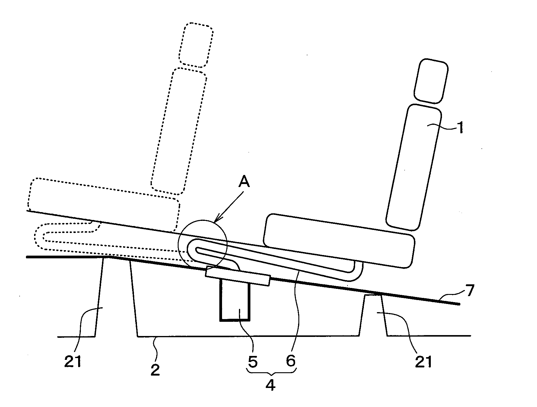
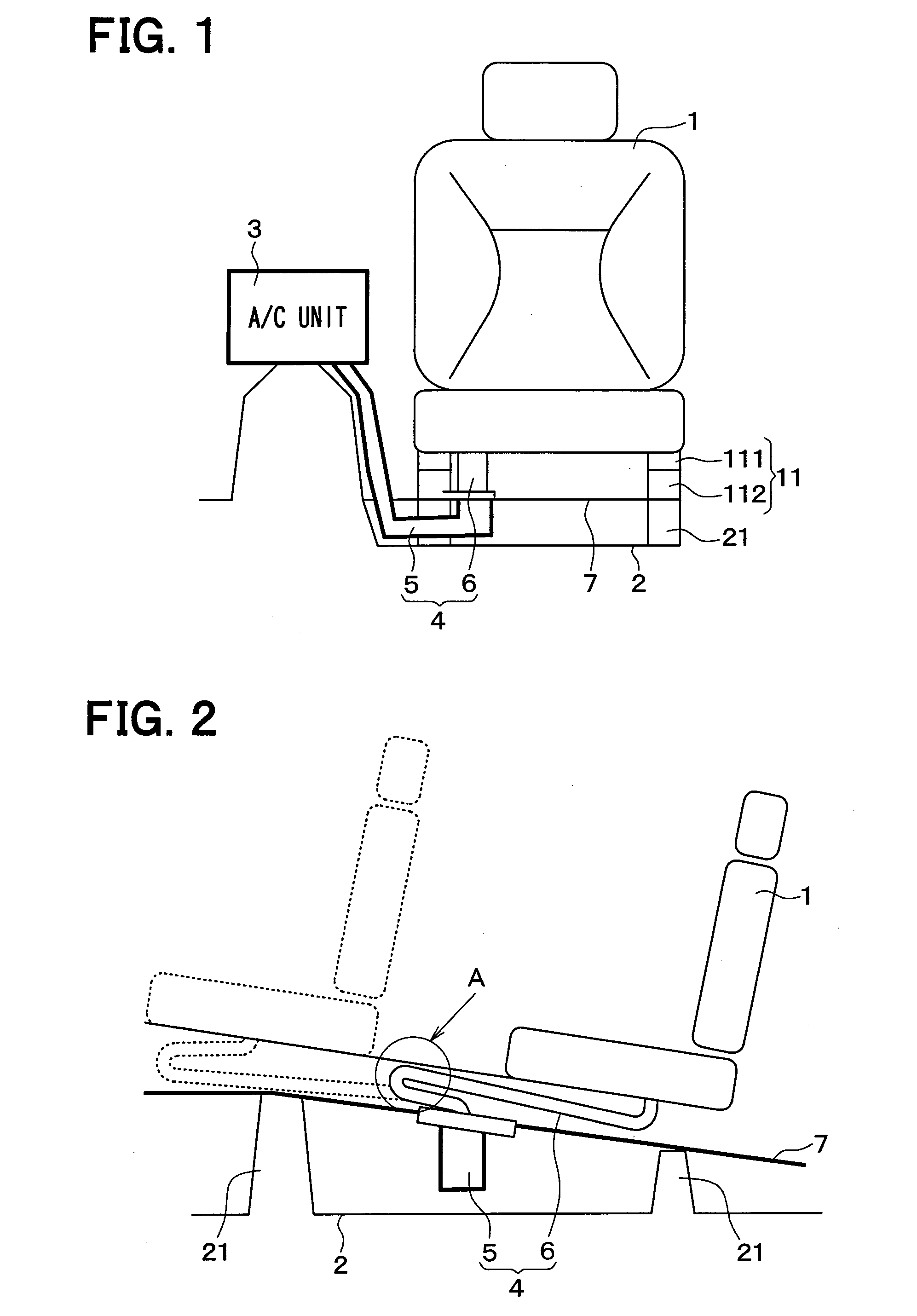
[0028]As shown in FIGS. 1 and 2, a seat 1 is fixed to a floor 2 of a vehicle body through a seat rail 11. The seat rail 11 adjusts a seating position of the seat 1 in a front-rear direction of a vehicle. The seat rail 11 has an upper rail 111 and a lower rail 112. The upper rail 111 is fixed to a back surface (i.e., a lower surface) of a seat portion of the seat 1. The lower rail 112 is fixed to a cross member 21 that is disposed on the floor 2. The upper rail 111 is slidable in the front-rear direction with respect to the lower rail 112.

[0029]A vehicle air conditioner has an interior air-conditioning unit 3 that performs an air conditioning for an indoor space of a vehicle compartment. The interior air-conditioning unit 3 is arranged on an inner side of a dashboard (i.e., an instrument panel) that is located on a foremost area of the vehicle compartment. The interior air-conditioning unit 3 has an air conditioning...

second embodiment

[0049]A first embodiment of the present disclosure will be described. According to the present embodiment, a structure of the connection duct is different from that of the first embodiment. Other configurations are similar to the first embodiment. Thus, a feature different from the first embodiment will be described hereafter.

[0050]As shown in FIGS. 8 through 11, a connection duct 8 has an outer plate 81 and an inner plate 82. The outer plate 81 has a plate shape and is located on an outer peripheral side in the curved portion. The inner plate 82 has a plate shape and is located on an inner peripheral side in the curved portion. The outer plate 81 and the inner plate 82 face each other to be a specified distance away from each other in a direction perpendicular to the flow direction B. A thickness of the outer plate 81 is larger than a thickness of the inner plate 82. Therefore, a rigidity of the outer plate 81 is higher than a rigidity of the inner plate 82.

[0051]As shown in FIGS. ...


PUM


Abstract

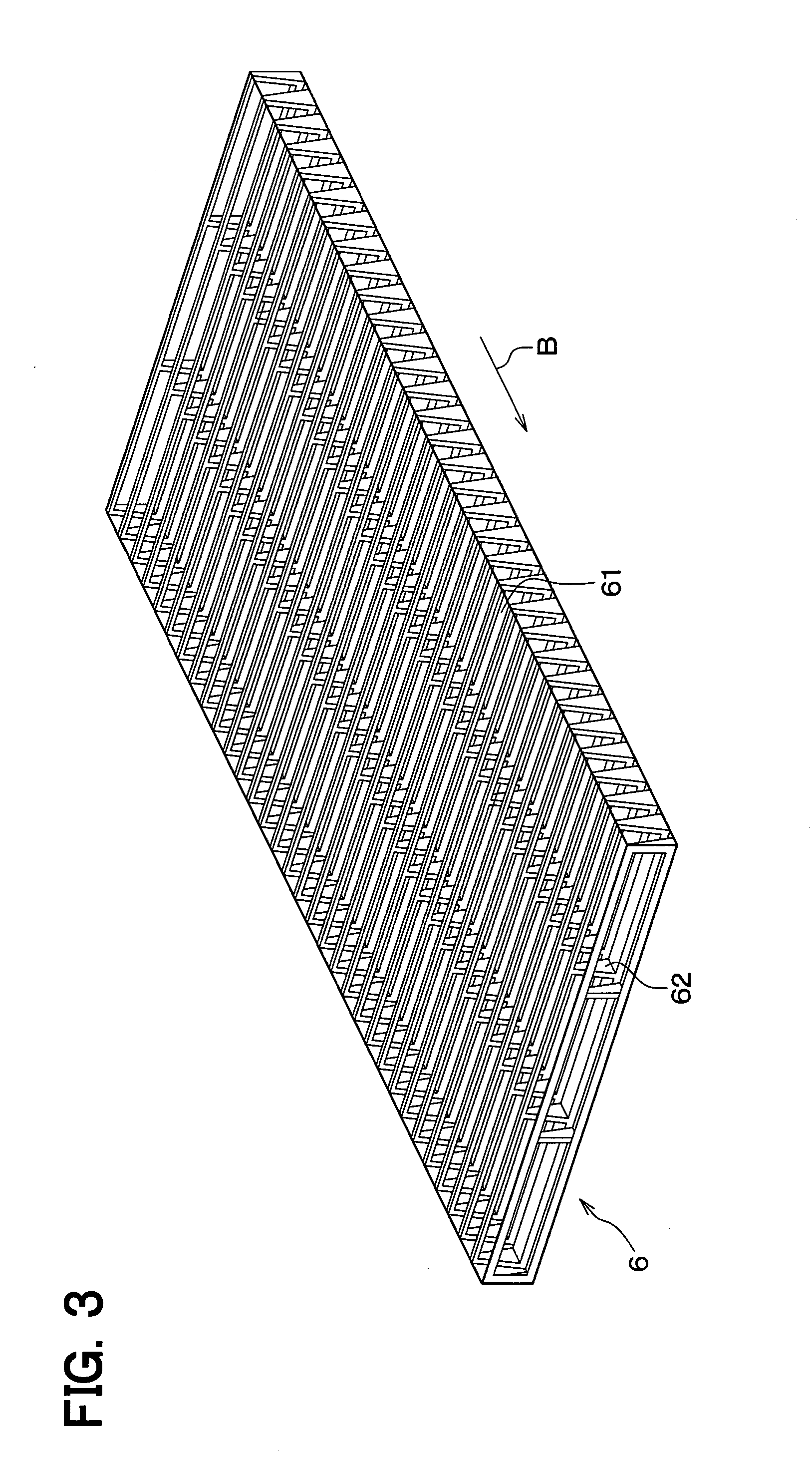
A connection duct has (i) a duct body that is made of a material having great flexibility, the duct body in which the conditioned air flows and (ii) core members that are made of a material having higher rigidity than the duct body and are arranged, in the duct body, along a flow direction of air, the core members that maintain a cross-sectional shape of the duct body at a specified cross-sectional shape. The core members respectively have (i) an outer plate that is located on an outer peripheral side in the curved portion, (ii) an inner plate that is located on an inner peripheral side in the curved portion, and (iii) a connection plate that connects the outer plate with the inner plate. A length of the outer plate in the flow direction is longer than a length of the inner plate in the flow direction.

Description

CROSS REFERENCE TO RELATED APPLICATION[0001]This application is based on Japanese Patent Application No. 2013-237987 filed on Nov. 18, 2013, the disclosure of which is incorporated herein by reference.TECHNICAL FIELD[0002]The present disclosure relates to a vehicle seat air-conditioning device that blows a conditioned air supplied from an interior air-conditioning unit.BACKGROUND ART[0003]Conventionally, such a vehicle seat air-conditioning device is known as described in, for example, Patent Literature 1. A vehicle seat air-conditioning device of Patent Literature 1 has a seat air-conditioning duct and a connection duct. The seat air-conditioning duct guides a conditioned air supplied from an interior air-conditioning unit to a location around a seat of a vehicle. The connection duct has one end fixed to the seat air-conditioning duct and the other end fixed to the seat, and guides the conditioned air to the seat.[0004]The connection duct has a portion (referred to as a bellows por...

Claims


Application Information

Patent Timeline
IPC IPC(8): B60H1/00B60N2/56
CPCB60H1/00564B60H1/00285B60N2/5657B60N2/5628B60H2001/003B60N2/06
Inventor FUJII, TAKAHISANIIMI, YASUHIKOTANAKA, YUUSUKE
Owner DENSO CORP
Learn More