Power transfer unit (PTU) assembly with hydraulically actuated disconnect rear output shaft

Active Publication Date: 2016-10-06
BORGWARNER INC
View PDF0 Cites 1 Cited by
  • Summary
  • Abstract
  • Description
  • Claims
  • Application Information

AI Technical Summary

Problems solved by technology

Typically, it is not desirable to use the transmission pump as a source of pressurized fluid since it is expensive to inc...

Method used


Image

  • Power transfer unit (PTU) assembly with hydraulically actuated disconnect rear output shaft
  • Power transfer unit (PTU) assembly with hydraulically actuated disconnect rear output shaft
  • Power transfer unit (PTU) assembly with hydraulically actuated disconnect rear output shaft

Examples


Embodiment Construction

[0018]The following description of the preferred embodiment(s) is merely exemplary in nature and is in no way intended to limit the invention, its application, or uses.

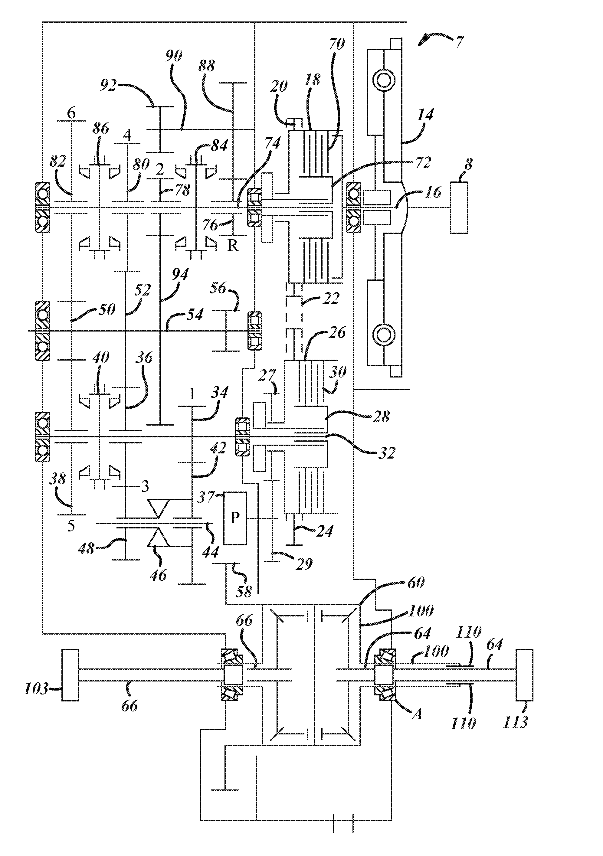
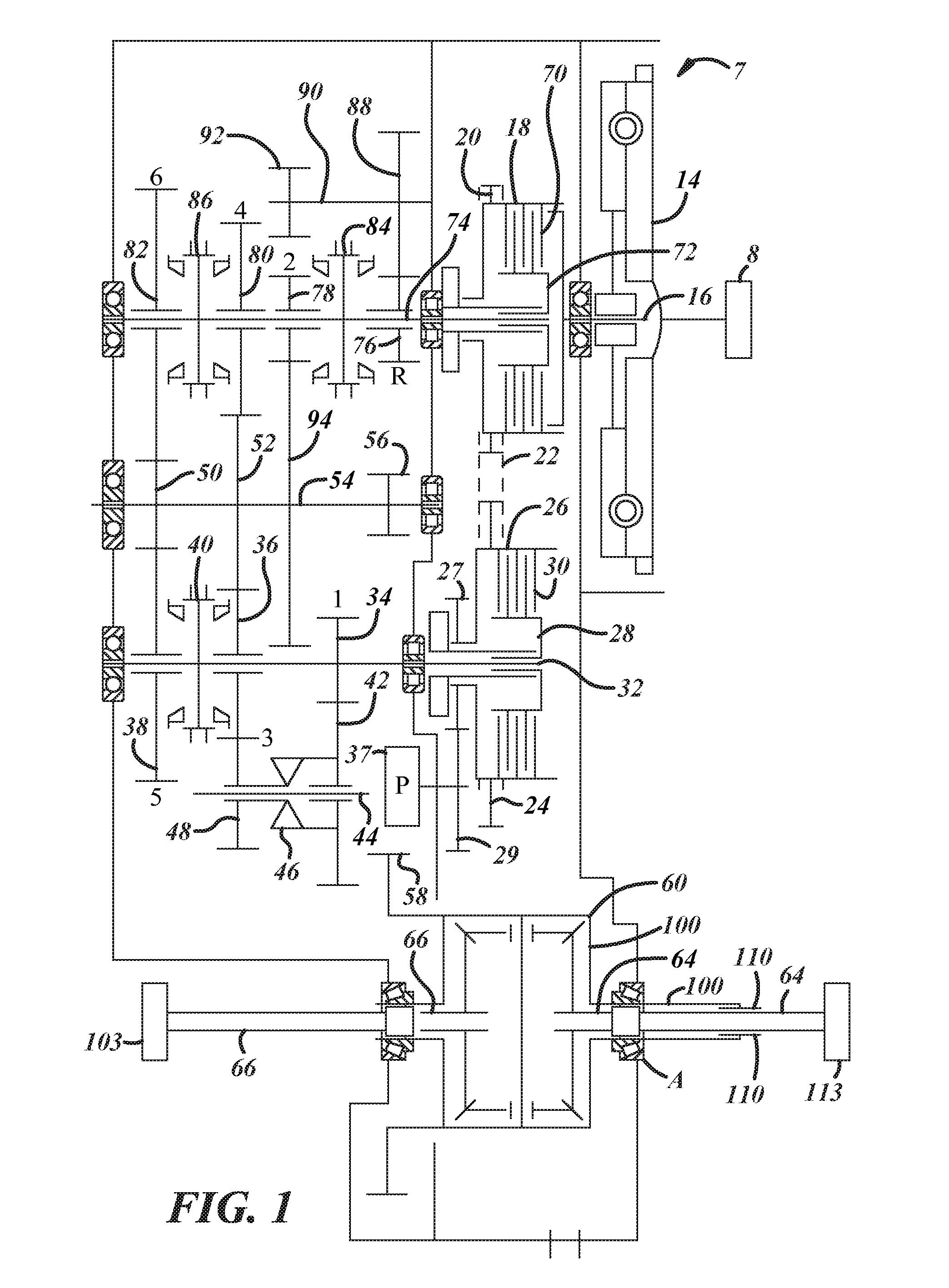
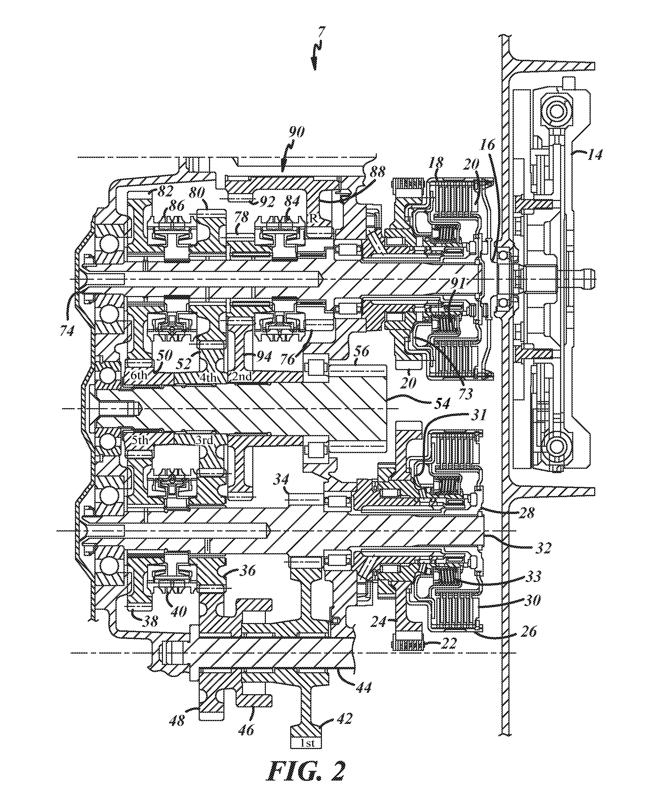
[0019]Referring to FIGS. 1, 2 and 3, a transverse mounted engine 8 of a normally front wheel drive selectively four wheel drive vehicle arrangement powers a six speed dual clutch transmission 7 of the present invention. The engine 8 typically will have a fly wheel connected with a damper 14. The damper is torsionally connected with a first clutch input shaft 16. The first clutch input shaft 16 is connected with a first clutch housing 18. The first clutch housing 18 is torsionally connected with a sprocket 20. The sprocket 20 is torsionally connected with a chain 22. The chain 22 is torsionally engaged with a second clutch housing sprocket 24. The second clutch housing sprocket 24 is fixably connected with a second clutch housing 26. The first clutch housing sprocket 20 has a diameter that is smaller than the diameter ...


PUM


Abstract

An arrangement of a vehicle is provided having normal transverse engine/transmission normal two-wheel drive operation which can be selectively placed into four-wheel drive operation wherein a pump which powers the coupling or uncoupling is independent of the transmission lubrication pump and is powered by the transmission.

Description

CROSS-REFERENCE TO RELATED APPLICATIONS[0001]This application claims the benefit of U.S. Patent Application No. 62 / 142,137 filed on Apr. 2, 2015, the disclosure of which is herein incorporated by reference in its entirety.FIELD OF THE INVENTION[0002]The present invention relates to arrangement of front wheel drive vehicles having transverse mounted engines with four wheel drive capabilities upon demand.BACKGROUND OF THE INVENTION[0003]To increase fuel economy, many vehicles have been switched over to front wheel drive so that the vehicle engine's weight can be over the main traction axle of a vehicle. To further increase fuel economy, many front wheel drive vehicles utilize a transverse mounted engine and transmission. To provide improved performance in inclement weather, many vehicles have selective four wheel drive capabilities. Typically in most front wheel drive vehicles with four wheel drive capability, the transmission powers a front differential. Torsionally downstream of the...

Claims


Application Information

Patent Timeline
IPC IPC(8): B60K17/344F15B11/10B60K17/354F16H57/04F16H48/08F16H37/08F16H57/037
CPCB60K17/344F16H37/0813F15B11/10B60K17/354F16H57/0436F16H48/08F16H57/037B60K17/35B60K17/3515B60K23/0808B60K2023/0866
Inventor RODE, JOHN H.CRADIT, JEREMY L.FELDT, KEITH V.
Owner BORGWARNER INC
Why Eureka
Try Eureka