Synchronizer-mechanism-equipped transmission

a technology of synchronizer and motor, applied in the field of transmission, can solve the problem of almost no friction resistance to the movement of the sleeve teeth back, and achieve the effect of reducing the weight of the transmission

Active Publication Date: 2016-10-06
HONDA MOTOR CO LTD
View PDF12 Cites 6 Cited by
  • Summary
  • Abstract
  • Description
  • Claims
  • Application Information

AI Technical Summary

Benefits of technology

[0022]According to an embodiment of the present invention, a detent mechanism of a simple structure is used. In the detect mechanism, a roller that is pivotally supported on the tip of the detent arm biased by the biasing means comes into contact with and presses the uneven cam surface of the star cam. This allows the detent mechanism to be compactly incorporated into the transmission for downsizing and for a weight reduction of the transmission.
[0023]According to an embodiment of the present invention, when the sleeve teeth of the synchronizer sleeve that moves during gear shifting are located at the first synchronization position where the sleeve teeth begin to come into contact with the ring teeth, the pressing member of the detent mechanism is in contact with the pre-gear-shifting detent recessed portion of the star cam. Therefore, even if actuator driving stops at the first synchronization position, there is almost no frictional resistance to the movement of the sleeve teeth back to where the sleeve teeth were before the sleeve teeth came into contact with the ring teeth. Therefore, the biasing means causes the pressing member to come into contact with and press the sloped surface of the pre-gear-shifting detent recessed portion of the star cam, rotating the star cam with almost no resistance and bringing the shift drum back to the predetermined pre-gear-shifting rotation position and moving the synchronizer sleeve of the synchronizer mechanism back to its initial proper position. This moves the tips of the sleeve teeth and ring teeth away from butting with each other.

Problems solved by technology

As a result, there is almost no frictional resistance to the movement of the sleeve teeth back to where the sleeve teeth were before the sleeve teeth came into contact with the ring teeth.

Method used


Image

  • Synchronizer-mechanism-equipped transmission
  • Synchronizer-mechanism-equipped transmission
  • Synchronizer-mechanism-equipped transmission

Examples


first embodiment

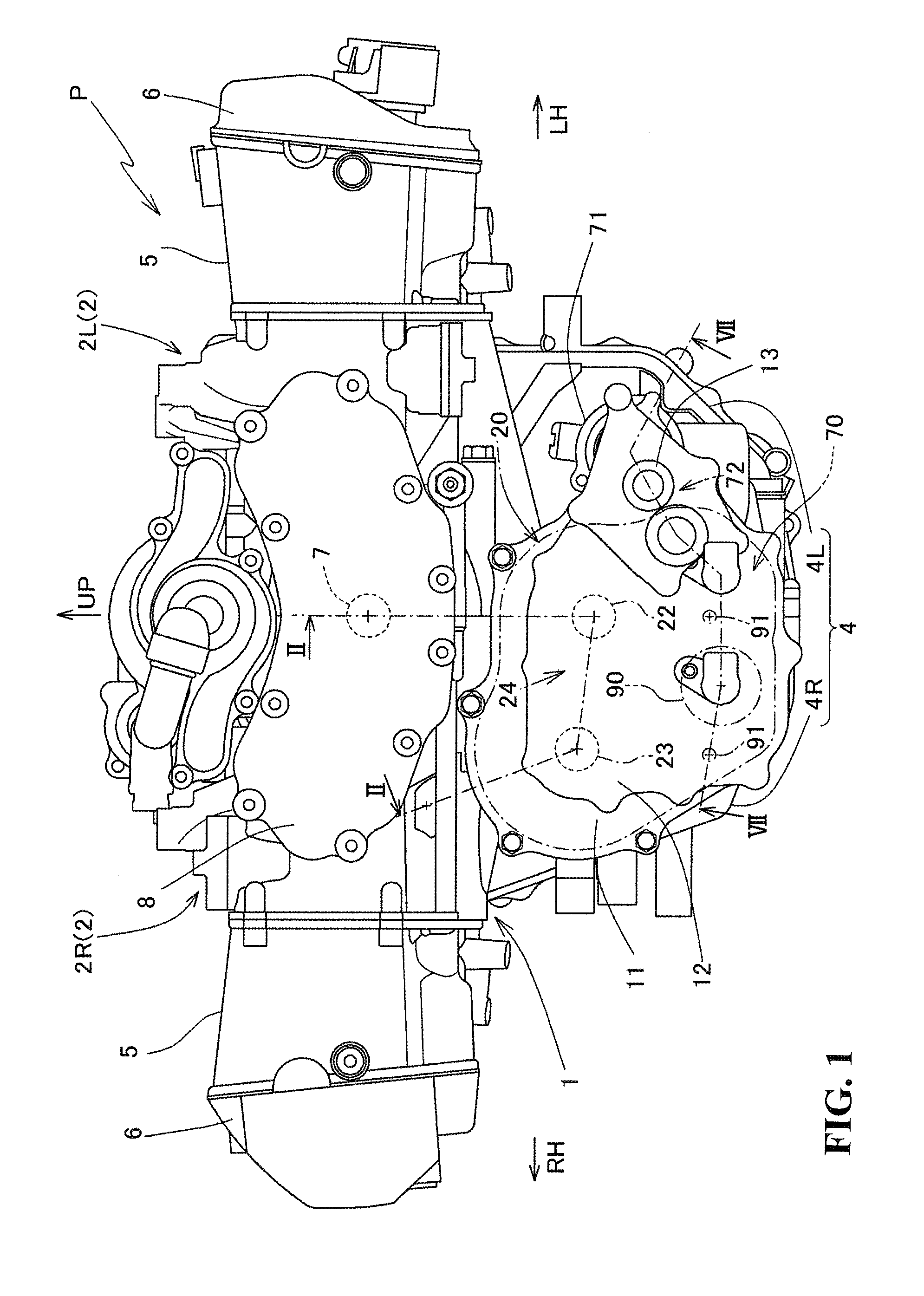
[0037]FIG. 1 is a partially omitted front view of a power unit P used for a synchronizer-mechanism-equipped transmission 20 according to the present invention.

[0038]The power unit P is mounted to a motorcycle and includes an internal combustion engine 1 and the synchronizer-mechanism-equipped transmission 20. The internal combustion engine 1 is a so-called vertically mounted, horizontally opposed six cylinder water-cooled four stroke cycle engine with a crankshaft 7 running longitudinally along the vehicle. The transmission 20 is coupled to the internal combustion engine 1 and shifts power of the internal combustion engine 1 to a predetermined gear position.

[0039]It should be noted that, in the present specification, the longitudinal and horizontal orientations are as per normal criteria that consider the direction in which the motorcycle moves straight ahead as forward.

[0040]Further, the forward, rearward, leftward, rightward, upward, and downward directions in the drawings are den...


PUM


Abstract

A synchronizer-mechanism-equipped transmission capable of moving tips of sleeve teeth and ring teeth away from butting each other by moving a synchronizer sleeve with biasing means even if the tips of the sleeve teeth and ring teeth are in contact when actuator driving stops. When sleeve teeth of a synchronizer sleeve that moves during gear shifting are located at a first synchronization position where the sleeve teeth begin to come into contact with ring teeth, a pressing member of a detent mechanism is in contact with a pre-gear-shifting detent recessed portion of a star cam.

Description

CROSS-REFERENCE TO RELATED APPLICATIONS[0001]The present application claims priority under 35 USC 119 to Japanese Patent Application No. 2015-069994 filed Mar. 30, 2015 the entire contents of which are hereby incorporated by reference.BACKGROUND OF THE INVENTION[0002]1. Field of the Invention[0003]The present invention relates to a transmission. More particularly, to a synchronizer-mechanism-equipped transmission.[0004]2. Description of Background Art[0005]A synchronizer mechanism for a transmission is known. See, for example, Japanese Patent Laid-Open No. 2004-125112.[0006]In the synchronizer mechanism disclosed in Japanese Patent Laid-Open No. 2004-125112, ring gear teeth (ring teeth) formed on an outer ring (synchronizer ring) of a blocking ring come between gear teeth (gear dog teeth) and spline teeth (sleeve teeth). The gear teeth are formed on a first transmission gear that is pivotally supported in a relatively rotatable manner on each of main and counter shafts, each being a...

Claims


Application Information

Patent Timeline
Patent Type & Authority Applications(United States)
IPC IPC(8): F16H3/091F16D23/02F16D11/00F16H63/32
CPCF16H3/091F16H63/32F16H2063/321F16D11/00F16H2063/3093F16D23/02F16H3/006F16H2061/0474F16H61/04F16H63/18F16H63/38F16D23/06F16D2023/0681F16H63/30
Inventor TSUKADA, YOSHIAKIKANNO, YOSHIHISANAKAMURA, KAZUHIKOKOJIMA, HIROYUKIOZEKI, TAKASHITAKAMOTO, HIROSHI
Owner HONDA MOTOR CO LTD
Why Eureka
Try Eureka