In-ear headphones with noise reduction effect

a technology of in-ear headphones and noise reduction, applied in the field of communication, can solve the problems of narrow and inexact noise sampling directions, inability to achieve high-quality noise reduction effect, and in-ear headphones adopting double-microphone noise reduction schemes that are not researched and developed, so as to achieve better noise reduction effect and reduce noise

Inactive Publication Date: 2016-10-06
ZHONGMING DONGGUAN ELECTRONICS
View PDF10 Cites 15 Cited by
  • Summary
  • Abstract
  • Description
  • Claims
  • Application Information

AI Technical Summary

Benefits of technology

[0006]The invention aims to solve the disadvantages and disclose the in-ear headphones with the noise reduction effect. The in-ear headphones adopt the double-microphone structure to reduce noise and achieve the better noise reduction effect, and thus the in-ear headphones are more applicable to various high-noise environments.

Problems solved by technology

Generally, current headphones have the noise reduction function, and a microphone for acquiring sound samples is respectively arranged outside left and right earmuffs; with diversified and changeable external noise, only one earmuff can accommodate a full-noise sampling microphone so that noise sampling directions are narrow and inexact and the high-quality noise reduction effect cannot be achieved.
Due to restriction of the double-microphone installation structure, the in-ear headphones adopting the double-microphone noise reduction scheme are not researched and developed.
Besides, users feel uncomfortable at 250 Hz and 60 db, only the disadvantage of low-frequency noise can be reduced through the traditional active noise reduction technology; because the traditional technology has the smaller noise reduction depth and width, the total noise reduction ability is low.

Method used


Image

  • In-ear headphones with noise reduction effect
  • In-ear headphones with noise reduction effect
  • In-ear headphones with noise reduction effect

Examples


Embodiment Construction

[0028]The in-ear headphones are further elaborated according to Figures and specific embodiment.

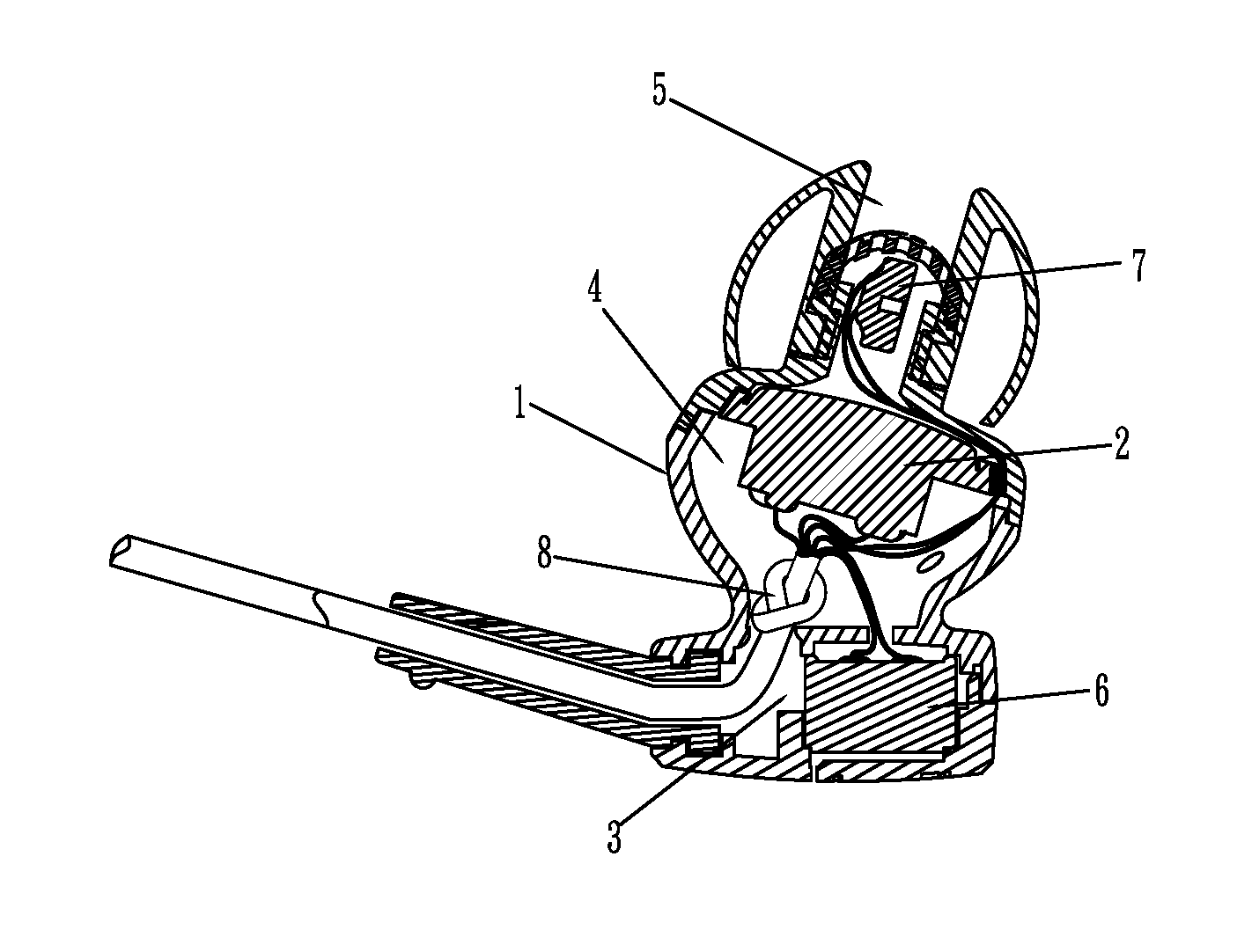
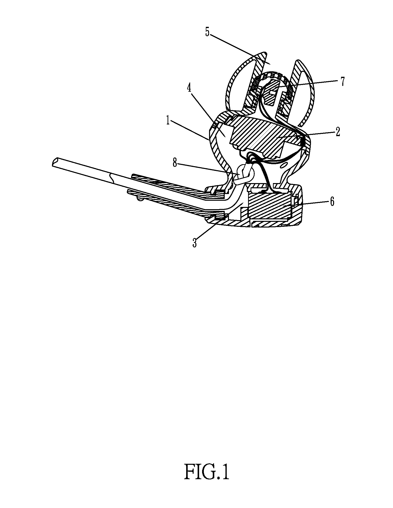
[0029]In the embodiment, please refer to FIG. 1 and FIG. 2, the in-ear headphones comprise the headphone shell 1 in which the sound making unit and the control circuit are installed, and the sound making unit of the embodiment is the high-fidelity loudspeaker 2. The control circuit and the sound making unit are interconnected, and the sound making unit is connected with the sound signal transmission line 8. The control circuit comprises the first detection unit, the second detection unit, the comparison unit, the calculation unit and the sound wave output unit.

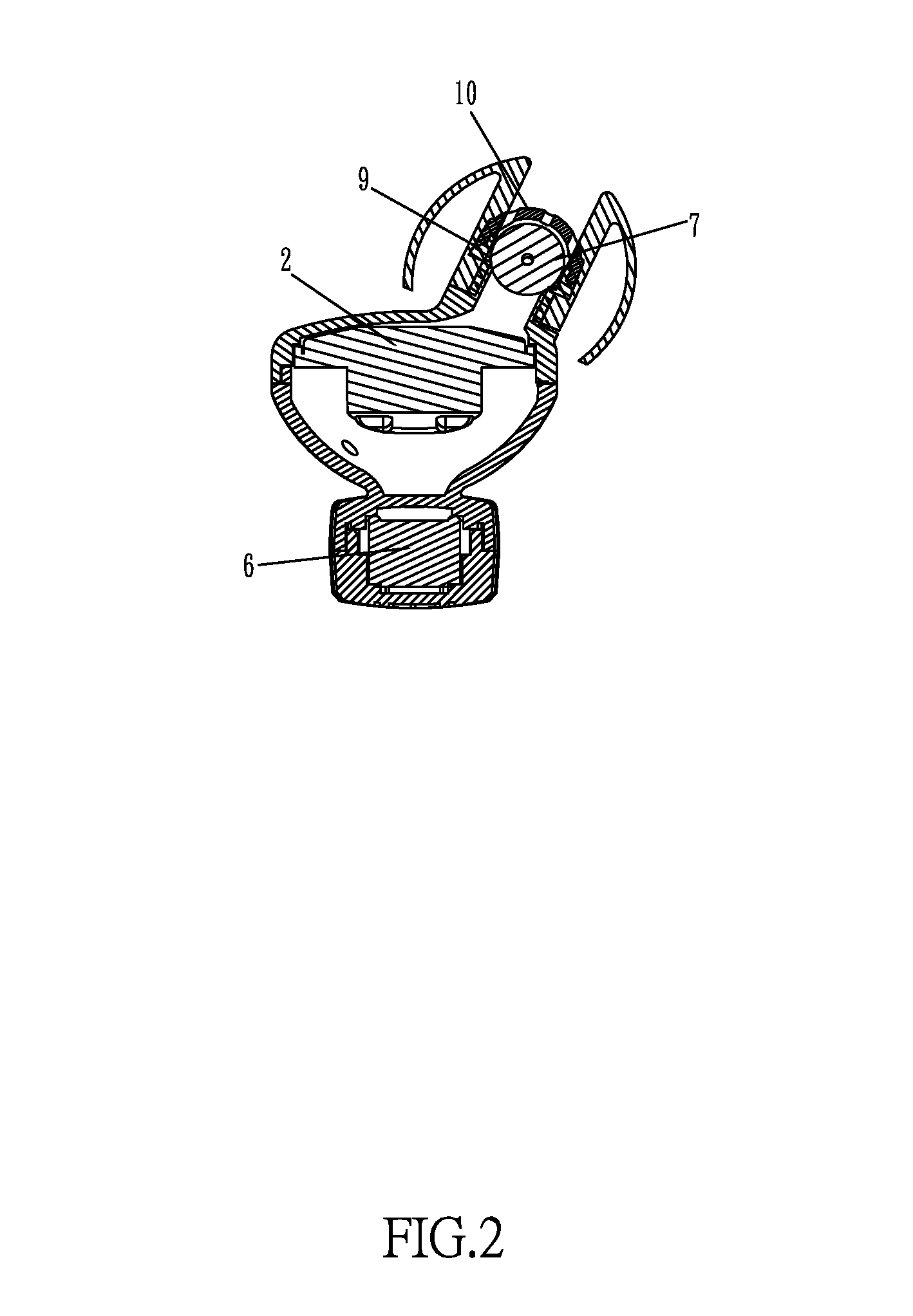
[0030]The first cavity 3, the second cavity 4 and the third cavity 5 are accommodated in the headphone shell 1, the first cavity 3 is located on the bottom of the headphone shell 1, the first microphone 6 is transversely installed in the first cavity 3 and the sound receiving side of the first microphone 6 is either upwards or downw...


PUM


Abstract

In-ear headphones comprise a headphone shell, wherein a sound making unit and a control circuit are installed in the headphone shell, a first cavity, a second cavity and a third cavity are accommodated in the headphone shell, a first microphone is transversely installed in the first cavity, a second microphone is vertically installed in the third cavity, and the first microphone and the second microphone are connected to the control circuit through a sound signal transmission line; the sound making unit is transversely installed in the second cavity, the sound making side of the sound making unit upwardly faces toward the sound making opening of the third cavity, and the second microphone is located above the sound making unit.

Description

BACKGROUND OF THE INVENTION[0001]1. Technical Field[0002]The invention relates to the technical field of communication, especially relates to headphones, and concretely relates to in-ear headphones with the noise reduction effect.[0003]2. Description of Related Art[0004]Common headphones are mainly composed of four parts: headbands, sound making units, earmuffs and leads; the headbands are used for fixing the earmuffs to ears, the leads are used for transmitting sound signals from sound boxes to sound making units, and the sound making units are arranged in the earmuffs. Generally, current headphones have the noise reduction function, and a microphone for acquiring sound samples is respectively arranged outside left and right earmuffs; with diversified and changeable external noise, only one earmuff can accommodate a full-noise sampling microphone so that noise sampling directions are narrow and inexact and the high-quality noise reduction effect cannot be achieved.[0005]In order to...

Claims


Application Information

Patent Timeline
Patent Type & Authority Applications(United States)
IPC IPC(8): G10K11/178H04R3/00H04R1/10H04W4/80
CPCG10K11/1784H04R1/1016H04R2460/01H04R3/005H04R1/1083H04R1/1058G10K2210/3219G10K2210/3226G10K11/17881G10K11/17857H04W4/80H04R1/1041H04R2420/07
Inventor YANG, SHAO-CONGLO, WAI-MINGWONG, ON-YUNG
Owner ZHONGMING DONGGUAN ELECTRONICS
Why Eureka
Try Eureka