Light emitting device

Active Publication Date: 2016-10-06
LUMIMICRO CORP
View PDF2 Cites 4 Cited by
  • Summary
  • Abstract
  • Description
  • Claims
  • Application Information

AI Technical Summary

Benefits of technology

This patent describes a way to make a light emitting device that produces white light and looks natural blue. This is done by improving a specific value called R12 and the overall color rendering index. This technology can help create more high-quality lighting that is more useful in a variety of situations.

Problems solved by technology

However, there is a problem in which a color rendering index (CRI) is low because of lack of a spectrum of green and red due to the emission of a single yellow phosphor.
However, although such a technology improves the general CRI Ra, there is a problem in that the value of R12 (blue) among the special CRIs is still low.

Method used


Image

  • Light emitting device
  • Light emitting device
  • Light emitting device

Examples


first embodiment

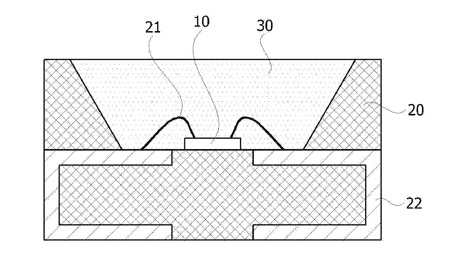
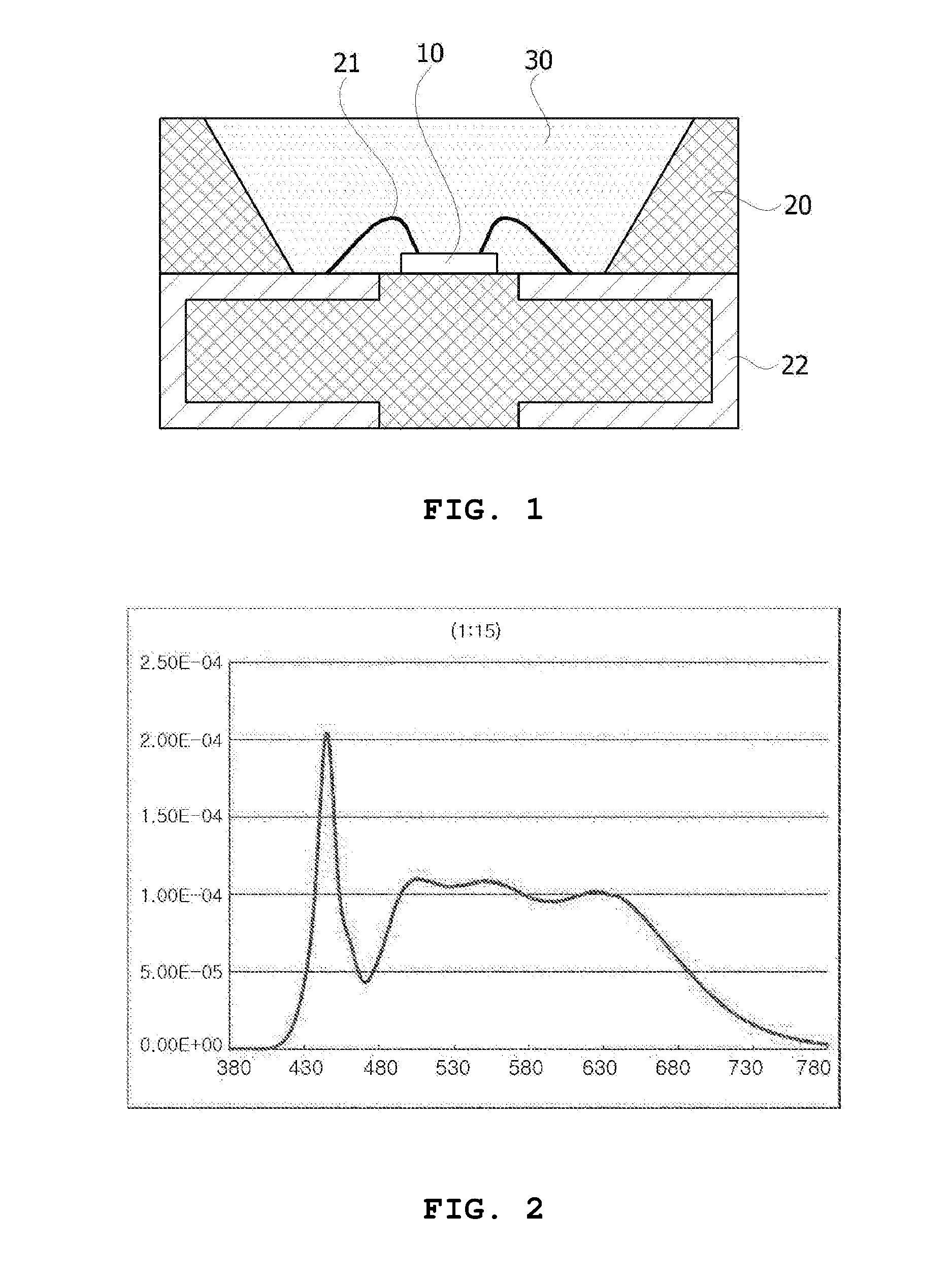
[0072]A compound phosphor at 12.5 wt % and a sealing material at 87.5 wt % were mixed and coated on a blue LED chip with a size of 1000 μm×500 μm and a peak wavelength of 446.3 nm. The compound phosphor was manufactured by mixing a first phosphor (BaSi2O2N2:Eu2+) having a peak wavelength of 497 nm at 5.4 wt %, a second phosphor (Lu3Al5O12:Ce3+) having a peak wavelength of 520 nm at 80.7 wt %, and a third phosphor (CaAlSiN3) having a peak wavelength of 650 nm at 13.9 wt % into the sealing material. Here, ratios of the phosphors were calculated based on 100 wt %. The ratio of the first phosphor to the second phosphor was 1:15. A spectrum of light emitted from a manufactured white LED is illustrated in FIG. 2, and a CRI evaluation table is illustrated in FIG. 3.

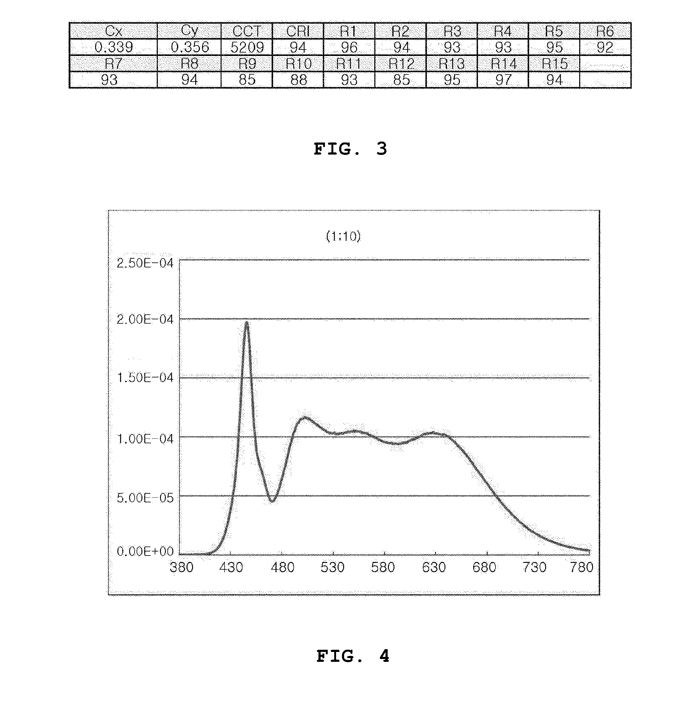
[0073]Referring to FIG. 3, all CRI values of R1 to R15 were 80 or more, and R12 was measured to be a very high value of 85.

second embodiment

[0074]A compound phosphor at 13.3 wt % and a sealing material at 86.7 wt % were mixed and coated on a blue LED chip with a size of 1000 μm×500 μm and a peak wavelength of 446.3 nm. The compound phosphor was manufactured by mixing a first phosphor (BaSi202N2:Eu2±) having a peak wavelength of 497 nm at 7.7 wt, a second phosphor (Lu3Al5O12:Ce3+) having a peak wavelength of 520 nm at 76.9 wt %, and a third phosphor (CaAlSiN3) having a peak wavelength of 650 nm at 15.4 wt % into the sealing material. Here, a ratio of the first phosphor to the second phosphor was 1:10.

[0075]A spectrum of light emitted from the manufactured white LED is illustrated in FIG. 4, and a CRI evaluation table is illustrated in FIG. 5. Referring to FIG. 5, all CRI values of R1 to R15 were measured as 90 or more, and thus the CRI was greatly improved.

third embodiment

[0076]A compound phosphor at 13.9 wt % and a sealing material at 86.1 wt % were mixed and coated on a blue LED chip with a size of 1000 μm×500 μm and a peak wavelength of 446.9 nm. The compound phosphor was manufactured by mixing a first phosphor (BaSi2O2N2:Eu2+) having a peak wavelength of 497 nm at 10.5 wt %, a second phosphor (Lu3Al5O12:Ce3+) having a peak wavelength of 520 nm at 73.4 wt %, and a third phosphor (CaAlSiN3) having a peak wavelength of 650 nm at 16.1 wt % into the sealing material. A ratio of the first phosphor to the second phosphor was 1:7.

[0077]A spectrum of light of the manufactured white LED is illustrated in FIG. 6, and a CRI evaluation table is illustrated FIG. 7. Referring to FIG. 7, all CRI values of R1 to R15 were 80 or more, and a value of R12 was highly increased to 99.


PUM


Abstract

Disclosed is a light-emitting device which comprises: a light-emitting element for emitting a first light in a blue wavelength band; a first wavelength converter for converting the first light into a second light; a second wavelength converter for converting the first light into a third light; and a third wavelength converter for converting the first light into a fourth light, wherein the first to fourth lights have central wavelengths which satisfy the following relationship: [Expression 1]λ1<λ2<λ3<λ4 (wherein λ1 is the central wavelength of the first light; λ2 is the central wavelength of the second light; λ3 is the central wavelength of the third light; and λ4 is the central wavelength of the fourth light.)

Description

TECHNICAL FIELD[0001]The present invention relates to a light emitting device in which a color rendering index is improved.BACKGROUND ART[0002]A light emitting diode (LED) is a device in which a compound semiconductor such as GaAs, AlGaAs, GaN, and InGaInP is coated with a phosphor, and emits light having various colors. The LED converts a wavelength of light emitted from a light emitting diode (LED) to that of a required color using an outside phosphor.[0003]Conventionally, a method which converts a wavelength of light of a blue LED to that of white light using a yellow color phosphor has been used. The white LED having such a structure has been widely used because it has a low cost and is structurally simple in principle.[0004]However, there is a problem in which a color rendering index (CRI) is low because of lack of a spectrum of green and red due to the emission of a single yellow phosphor.[0005]The CRI is an index which evaluates how well an object of unique color is seen as a...

Claims


Application Information

Patent Timeline
IPC IPC(8): H01L33/50
CPCH01L33/504H01L33/502H01L2224/48091H01L2224/48247C09K11/59Y02B20/00C09K11/77347C09K11/77348H01L2924/00014H01L33/50C09K11/00
Inventor KIM, TAE HUNLEE, SANG IILEE, SANG JAECHOI, BONG YULLJI, BYUNG JOOHWANG, JE EUN
Owner LUMIMICRO CORP
Why Eureka
Try Eureka