Coextruded, multilayer and multicomponent 3D printing inputs field

a 3d printing and input technology, applied in the field of extrusion die systems, can solve the problems of increasing the complexity of identifying improved input materials, increasing the stability of products/models, etc., and achieves the effect of superior 3d object performance and high viscosity of the adjacent build material

Pending Publication Date: 2016-10-13
GUILL TOOL & ENG
View PDF9 Cites 190 Cited by
  • Summary
  • Abstract
  • Description
  • Claims
  • Application Information

AI Technical Summary

Benefits of technology

[0008]These inputs and specifically filaments enable layering or combining different materials simultaneously through one or more nozzles (preferably 1-6) during the so-called 3D printing process. These techniques facilitate smaller layer sizes (milli, micro, and nano) different layer configurations as well as the potential to incorporate materials that would otherwise not be usable in standard 3D printer methods.
[0051]Deposition speed is one unit of measure for distinguishing 3D printing methods. Extrusion rates ranging from about 800 mics to about 2,500 mics are common (Micro-cubic-inches-per-second (mics)). Additional parameters to describe the extruded melt include surface and a central regions, and further include viscosity profiles between the surface and the central region based in part on the axial temperature profile. A viscosity profile exhibiting a higher viscosity of the build material adjacent to the surface compared to the central region may yield superior 3D object performance.
[0057]The present invention relates to a 3-D nozzle or hot end further comprising an internal valve or stopgap mechanism which could block or temper flow of certain input filaments and / or raw materials, changing the output orientation and / or positioning of the product layers within the output product.

Problems solved by technology

Product / model stability likewise is demanding.
Restrictions on the suitability of materials adds to the complexity to identify improved input materials.

Method used


Image

  • Coextruded, multilayer and multicomponent 3D printing inputs field
  • Coextruded, multilayer and multicomponent 3D printing inputs field
  • Coextruded, multilayer and multicomponent 3D printing inputs field

Examples


Embodiment Construction

[0144]The present disclosure is generally directed towards to 3D printer inputs including filaments comprising separated layers or sections. These inputs particularly including filaments may be prepared by coextrusion, microlayer coextrusion or multicomponent / fractal coextrusion. As will be understood, the various diagrams, flow charts and scenarios described herein are only examples, and there are many other scenarios to which the present disclosure will apply.

Coextrusion

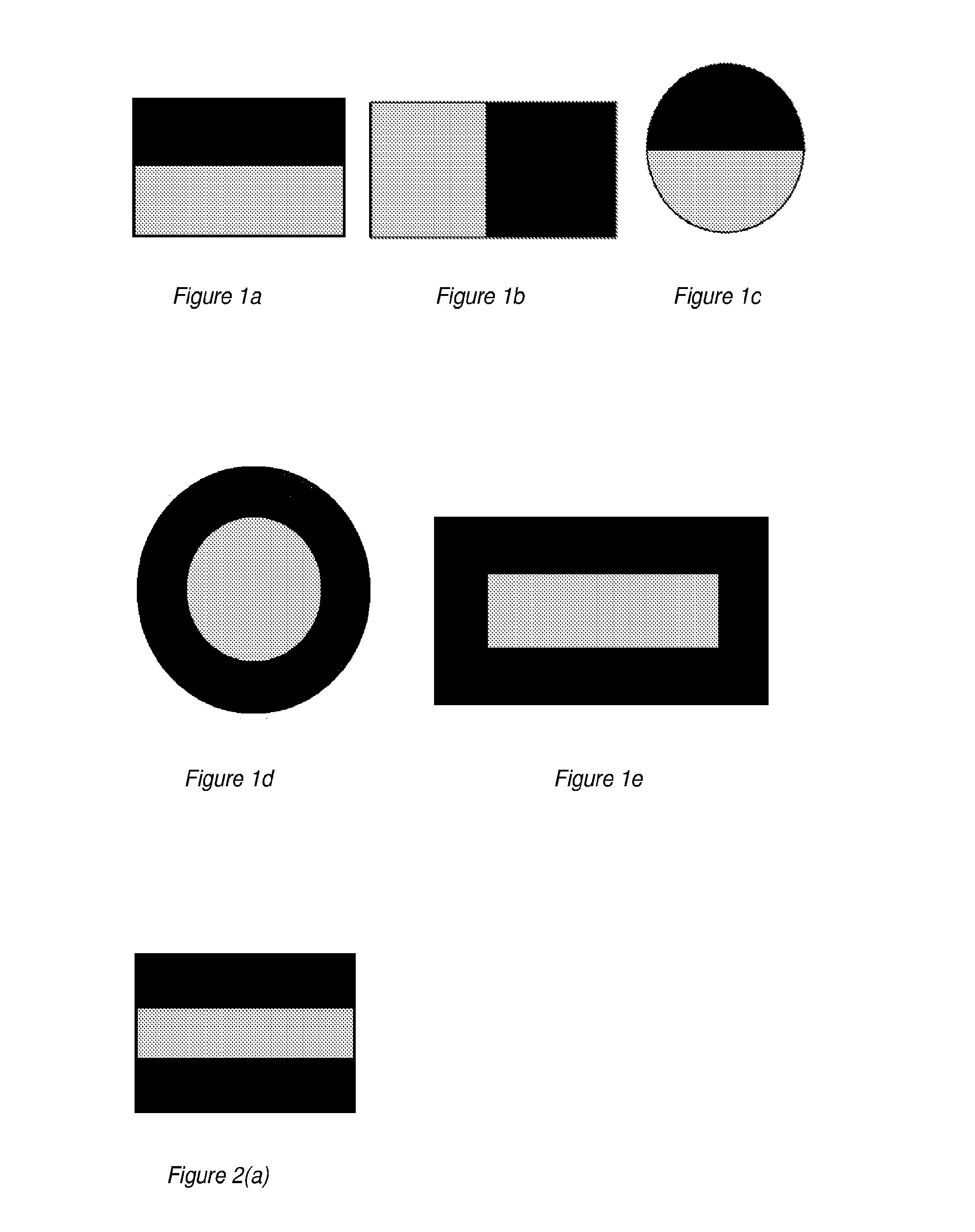
[0145]Coextrusion is the extrusion of more than one material or layer simultaneously. Materials can be layered together to form an extrudate with each material forming a portion of the cross section. Each layer can be any size or in any position relative to other layers. Some simple two layer products can be seen below in FIG. 1(a-e). These products can have layers in a flat orientation (FIG. 1(a-c)) or wrapped around themselves (FIG. 1(d,e)), or any combination of these orientations.

[0146]The input comprises two o...


PUM

PropertyMeasurementUnit
inner diameteraaaaaaaaaa
lengthsaaaaaaaaaa
conductiveaaaaaaaaaa

Abstract

The present invention relates to 3D printer inputs including filaments comprising separated layers or sections. These inputs particularly including filaments may be prepared by coextrusion, microlayer coextrusion or multicomponent / fractal coextrusion. These inputs and specifically filaments enable layering or combining different materials simultaneously through one or more nozzles during the so-called 3D printing process. These techniques facilitate smaller layer sizes (milli, micro, and nano) different layer configurations as well as the potential to incorporate materials that would otherwise not be usable in standard 3D printer methods.

Description

FIELD[0001]The present disclosure generally relates to extrusion die systems. In particular, the present disclosure relates to coextruded, multilayer, multicomponent tubular extrusions that are useful as inputs to three-dimensional fabrication machines. The present disclosure also relates to the design of extrusion heads and nozzles that extrude various laminae, including modifications and applications to the three-dimensional fabrication process.BACKGROUND OF THE INVENTION[0002]Various approaches to automated or semi-automated three-dimensional object production or Rapid Prototyping & Manufacturing (RP&M) have become available in recent years, characterized in that each proceeds by building up three dimensional objects from three dimensional computer data descriptive of the objects in an additive manner from a plurality of formed and adhered laminae. These laminae are sometimes called object cross-sections, layers of structure, object layers, layers of the object, or simply layers ...

Claims


Application Information

Patent Timeline
Patent Type & Authority Applications(United States)
IPC IPC(8): B29B11/16B29B11/10B33Y30/00B29C67/00B33Y70/00B29C48/05B29C48/02B29C48/18B29C48/21B29C48/71
CPCB29B11/16B29C67/0055B33Y70/00B33Y30/00B29K2105/162B33Y10/00B33Y40/00B29K2079/085B29B11/10B29C70/28B29C53/14B29C48/05B29C48/18B29C48/21B29C48/2886B29C48/71B29C64/118B29C64/106B29C48/0022B29C48/0021B29C48/022B29K2995/0003B29K2995/0018B29K2995/0065B29C69/001B29C66/69B33Y70/10D02G3/00B29C48/02D01D5/30
Inventor GUILLEMETTE, RICHARDPETERS, ROBERT
Owner GUILL TOOL & ENG
Why Eureka
Try Eureka