Methods for forming patterns in thin glass laminate structures

a technology of thin glass laminate and pattern, applied in the direction of special ornamental structures, layered products, chemistry apparatus and processes, etc., can solve problems such as optical distortion

Inactive Publication Date: 2016-10-13
CORNING INC
View PDF0 Cites 44 Cited by
  • Summary
  • Abstract
  • Description
  • Claims
  • Application Information

AI Technical Summary

Benefits of technology

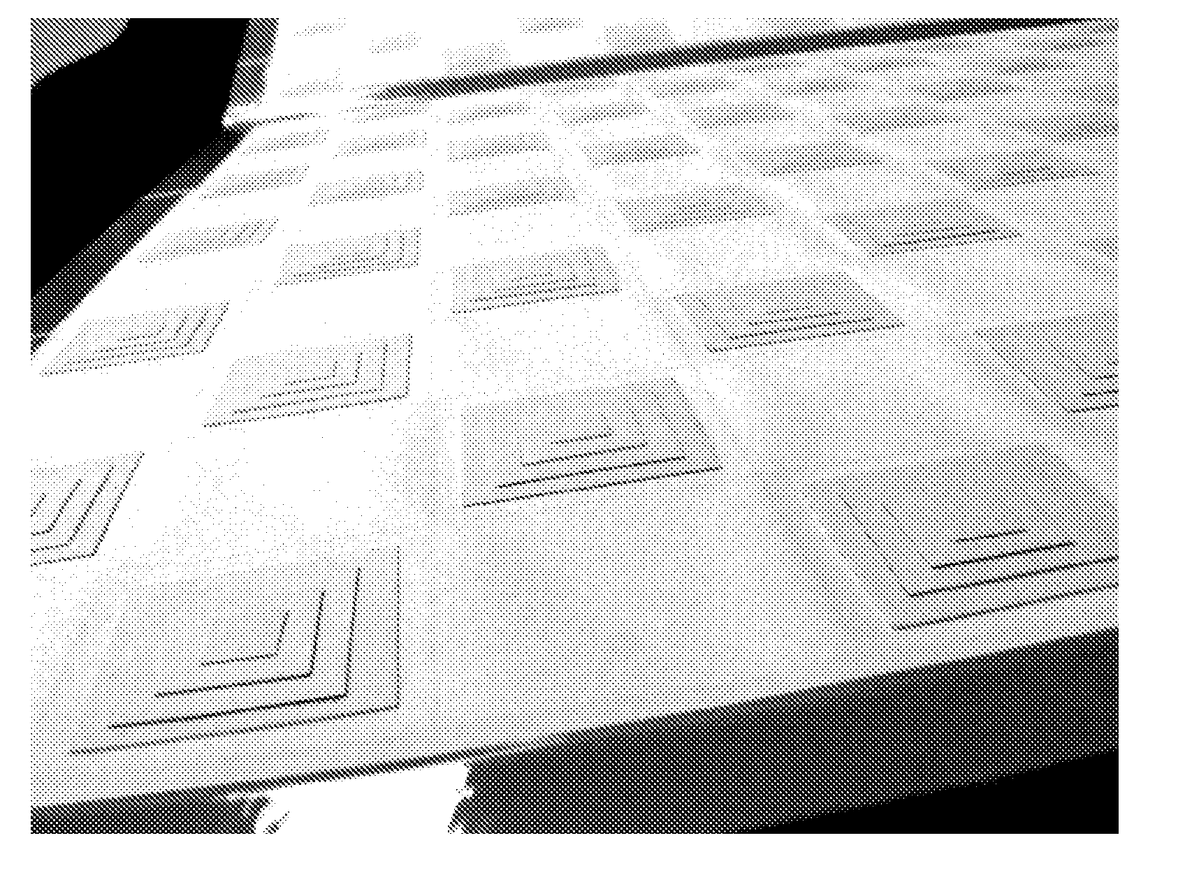
[0006]Some embodiments of the present disclosure provide a method of inducing a pattern in a glass laminate structure. The structure can include two layers of thin, strengthened glass and at least one layer of a thermoplastic interlayer material. The pattern can manifest itself as an induced optical distortion resulting from a change in thickness of the laminate between the area(s) of the pattern and adjacent background regions. In some embodiments, several diopters of optical power can be induced through these changes in laminate thicknesses. Additional embodiments can exploit the tendency of thin glass to deform during lamination which, in some cases, can result in optical distortions. By increasing the amount of distortion in a controlled manner, this tendency to deform can be utilized as an aesthetic improvement. Embodiments described herein can thus find utility in the area architectural laminate structures and can also find utility in other areas including, but not limited to, auto glazing, embossments, logos, and the like.

Problems solved by technology

Additional embodiments can exploit the tendency of thin glass to deform during lamination which, in some cases, can result in optical distortions.

Method used


Image

  • Methods for forming patterns in thin glass laminate structures
  • Methods for forming patterns in thin glass laminate structures
  • Methods for forming patterns in thin glass laminate structures

Examples


Embodiment Construction

[0019]In the following description, like reference characters designate like or corresponding parts throughout the several views shown in the figures. It is also understood that, unless otherwise specified, terms such as “top,”“bottom,”“outward,”“inward,” and the like are words of convenience and are not to be construed as limiting terms. In addition, whenever a group is described as comprising at least one of a group of elements and combinations thereof, it is understood that the group may comprise, consist essentially of, or consist of any number of those elements recited, either individually or in combination with each other.

[0020]Similarly, whenever a group is described as consisting of at least one of a group of elements or combinations thereof, it is understood that the group may consist of any number of those elements recited, either individually or in combination with each other. Unless otherwise specified, a range of values, when recited, includes both the upper and lower l...


PUM

PropertyMeasurementUnit
thicknessaaaaaaaaaa
thicknessaaaaaaaaaa
thicknessaaaaaaaaaa

Abstract

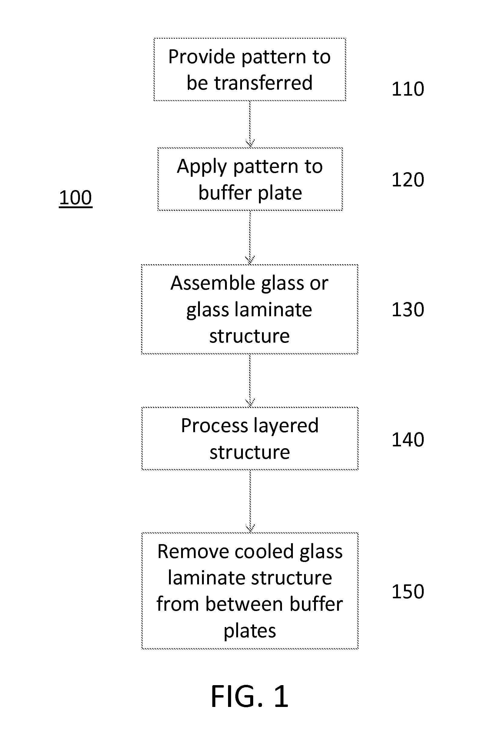
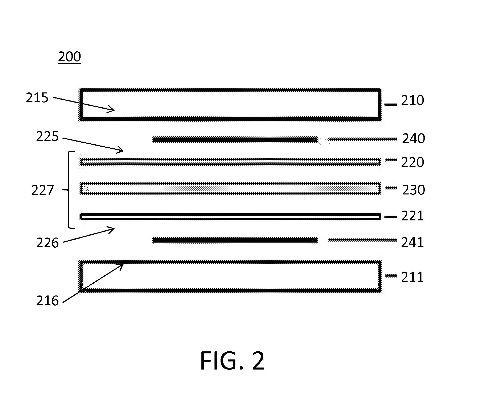
A method of cold forming a glass laminate structure. The method includes assembling a multi-layer structure having two buffer plates and a glass laminate structure intermediate the two buffer plates, wherein one or both of the two buffer plates includes a pattern formed thereon or therein or the multi-layer structure includes non-deformable materials forming a pattern. The method further includes cold forming the glass laminate structure in the autoclave by heating the assembled structure to a temperature about 5 to 10 degrees above the softening point of the polymer interlayer for a predetermined period of time at a predetermined pressure. After processing the glass laminate structure can be removed from between the buffer plates wherein the pattern formed in or on the one or both buffer plates or non-deformable materials has been transferred to the glass laminate structure as a function of variances of thicknesses in the glass laminate structure.

Description

[0001]This application claims the benefit of priority to U.S. Application No. 61 / 912797 filed on Dec. 6, 2013 the content of which is incorporated herein by reference in its entirety.BACKGROUND[0002]Glass laminate structures can be used as windows and glazing in architectural and transportation applications, including automobiles, rolling stock, locomotives and airplanes. Glass laminate structures can also be used as glass panels in balustrades and stairs, and as decorative panels or coverings for walls, columns, elevator cabs, kitchen appliances and other applications. As used herein, a glazing or a laminated glass structure can be a transparent, semi-transparent, translucent or opaque part of a window, panel, wall, enclosure, sign or other structure. Common types of glazings that are used in architectural and / or vehicular applications can include clear and tinted glass laminate structures.[0003]Conventionally, to form a pattern in a sheet of glass it is necessary to heat the glass...

Claims


Application Information

Patent Timeline
Patent Type & Authority Applications(United States)
IPC IPC(8): B32B17/10B32B37/14B32B37/06
CPCB32B17/10B32B2307/30B32B37/14B32B37/06B32B17/10036B32B17/10247B32B17/10743B32B17/10761B32B17/10853B32B17/10889B44C5/0407B44F1/066
Inventor RICKERL, PAUL GEORGE
Owner CORNING INC
Why Eureka
Try Eureka