
Evaporated fuel processing device

a technology of evaporation fuel and processing device, which is applied in the direction of electric control, charge feed system, and fuel addition of non-fuel substances, can solve the problem of insufficient influence of pressure release, and achieve the effect of easy control of pressure releas

Active Publication Date: 2016-10-13
AISAN IND CO LTD
View PDF7 Cites 9 Cited by
  • Summary
  • Abstract
  • Description
  • Claims
  • Application Information

AI Technical Summary

Benefits of technology

The present invention relates to an evaporated fuel processing device for vehicles. The device includes a canister, vapor passage, purge passage, shutoff valve, storage device, and control device. The canister adsorbs evaporated fuel from the fuel tank, and the vapor passage connects the canister to the fuel tank. The purge passage connects the canister to the engine's intake passage. The shutoff valve is adjusted based on the fuel tank pressure to control the flow of gas. The control device detects the pressure and adjusts the shutoff valve accordingly. This allows for easy control of the pressure in the fuel tank and ensures optimal engine performance. The control device can also determine the amount of fuel and air supplied to the engine and adjust the shutoff valve accordingly to restore the air-fuel ratio to normal. The shutoff valve has a movable valve that can be adjusted to fine-tune the flow rate of gas. Overall, the invention provides a reliable and efficient solution for controlling evaporated fuel processing in vehicles.

Problems solved by technology

When, for example, the amount of evaporated fuel generated in the fuel tank is large, there is a case where pressure release cannot be affected to a sufficient degree even when the shutoff valve is opened based on the reference value.

Method used


Image

  • Evaporated fuel processing device
  • Evaporated fuel processing device
  • Evaporated fuel processing device

Examples


Embodiment Construction

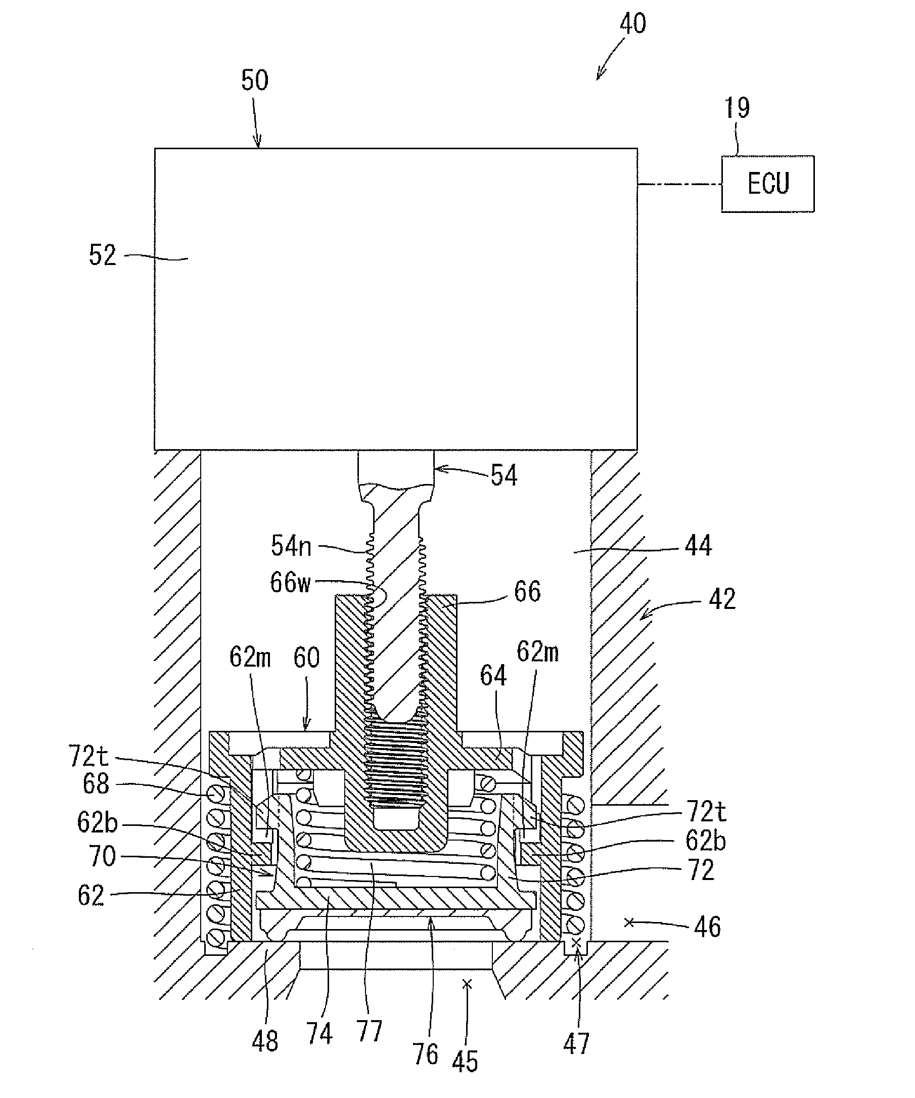
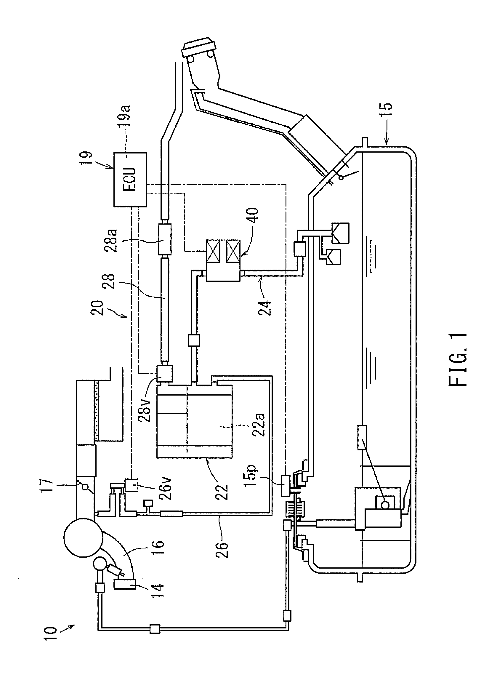
[0029]An embodiment of the present invention will be described with reference to the drawings. As shown in FIG. 1, an evaporated fuel processing device 20 is provided in a vehicle engine system 10. The evaporated fuel processing device 20 is a device for preventing evaporated fuel generated in a vehicle fuel tank 15 from leaking to the outside.

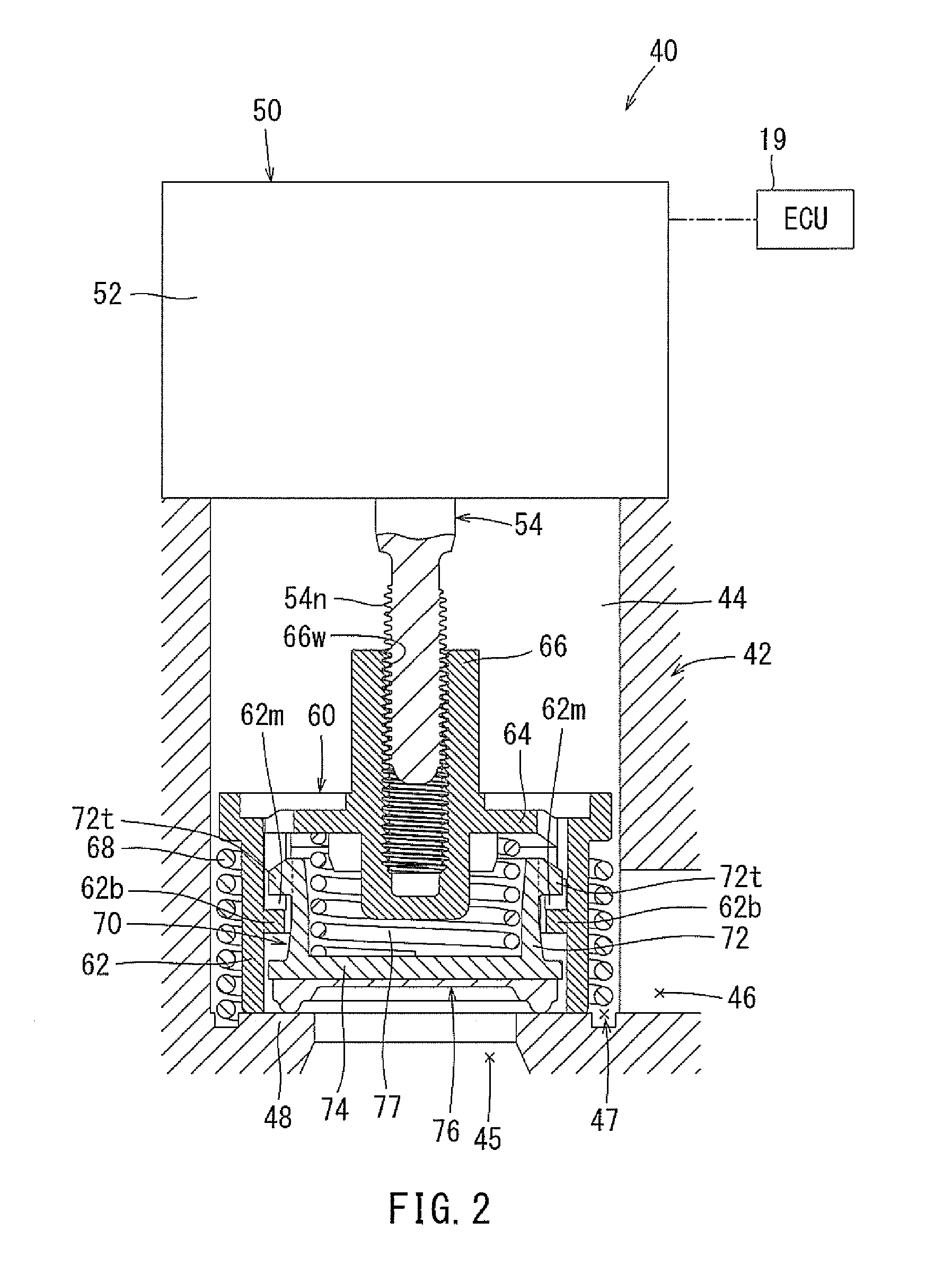
[0030]As shown in FIG. 1, the evaporated fuel processing device 20 has a canister 22, a vapor passage 24, a purge passage 26, and an atmosphere passage 28. The canister 22 contains activated carbon (not shown) as an adsorbent material 22a. The adsorbent material 22a adsorbs the evaporated fuel in the fuel tank 15. One end (the upstream side end) of the vapor passage 24 communicates with a gas space in the fuel tank 15. The other end (the downstream side end) of the vapor passage 24 communicates with the interior of the canister 22. A shutoff valve 40 that allows and interrupts communication through the vapor passage 24 is provided at some midp...


PUM


Abstract

An evaporated fuel processing device has a canister, a vapor passage, a purge passage, a shutoff valve, a storage device and a control device. The canister includes an adsorbent material that adsorbs evaporated fuel generated in a fuel tank. The vapor passage connects the canister and the fuel tank. The purge passage connects the canister and an intake passage of an engine. The shutoff valve is provided in the vapor passage, and adjusts flow rate of gas flowing through the vapor passage. The storage device stores in advance a reference value for the shutoff valve corresponding to internal pressure of the fuel tank. The shutoff valve is controlled based on the reference value, which is obtained from the internal pressure of the fuel tank, and pressure release control is performed on the fuel tank.

Description

CROSS-REFERENCE TO RELATED APPLICATIONS[0001]The present application is a National Phase entry of, and claims priority to, PCT Applicant No. PCT / JP2014 / 072940, filed Sep. 1, 2014, which claims priority to Japanese Patent Application No. 2013-243001, filed Nov. 25, 2013, both of which are incorporated herein by reference in their entireties.STATEMENT REGARDING FEDERALLY SPONSORED RESEARCH OR DEVELOPMENT[0002]Not applicable.BACKGROUND[0003]The present invention relates to an evaporated fuel processing device.[0004]An evaporated fuel processing device disclosed in JP2005-155323A has a canister, a shutoff valve, and a purge passage. The canister includes an adsorbent material for adsorbing evaporated fuel generated in a fuel tank. The shutoff valve is provided in a vapor passage connecting the canister and the fuel tank. The purge passage connects the canister and an intake passage of an engine. While the engine is driven, a predetermined purge condition is satisfied. At this time, the ...

Claims


Application Information

Patent Timeline
IPC IPC(8): F02M25/08
CPCF02M25/0836F02M25/0872F02M25/0854F02M25/089F02M2025/0845F02M25/08F02M37/10F02D41/0032F02D41/1454F02D41/0045
Inventor KIMOTO, JUNYAMIYABE, YOSHIKAZUTAGAWA, NAOYUKI
Owner AISAN IND CO LTD
Learn More