Ceramic heat exchange plate and ceramic heat exchange core assembled therby

Active Publication Date: 2016-10-13
CAS SUPER ENERGY TECH JINGJIANG
View PDF10 Cites 3 Cited by
  • Summary
  • Abstract
  • Description
  • Claims
  • Application Information

AI Technical Summary

Benefits of technology

[0013]The present invention is reasonable in structure and convenient to manufacture, and improves the air tig

Problems solved by technology

With regard to the first core, the ceramic spacers are likely to generate an internal stress and thus to crack due to the bonding of the corrugated ceramic slices

Method used


Image

  • Ceramic heat exchange plate and ceramic heat exchange core assembled therby
  • Ceramic heat exchange plate and ceramic heat exchange core assembled therby
  • Ceramic heat exchange plate and ceramic heat exchange core assembled therby

Examples


Example

IN THE DRAWINGS

[0021]3: side sealing strip;[0022]41: U-shaped groove;[0023]42: inverted U-shaped groove;[0024]43: top linear sealing groove;[0025]44: bottom linear sealing groove;[0026]45: □-shaped groove A;[0027]46: □-shaped groove B;[0028]50: end face porthole;[0029]51: side face porthole;[0030]100: ceramic heat exchange plate A;[0031]101: first corner;[0032]102: second corner;[0033]103: third corner;[0034]104: fourth corner;[0035]111: first side;[0036]112: second side;[0037]113: third side;[0038]114: fourth side;[0039]120: central heat exchange plate;[0040]121: upper fin;[0041]122: lower fin;[0042]200: ceramic heat exchange plate B; and[0043]900: ceramic heat exchange core.

DETAILED DESCRIPTION OF THE INVENTION

[0044]The present invention will be further described as below with reference to the accompanying drawings.

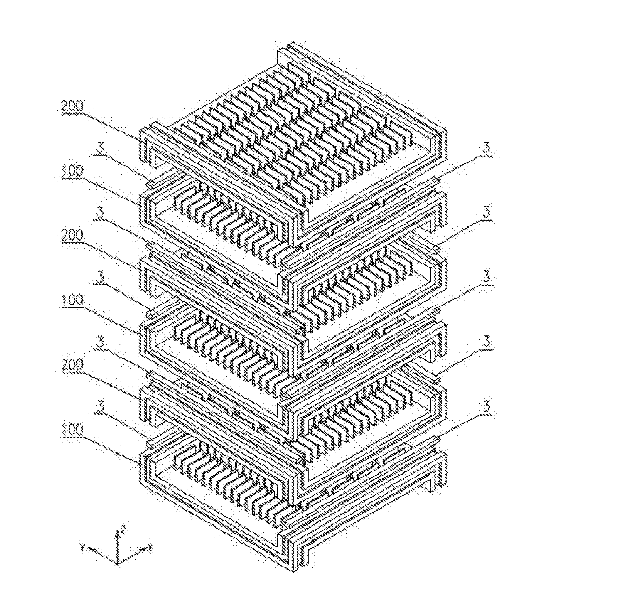
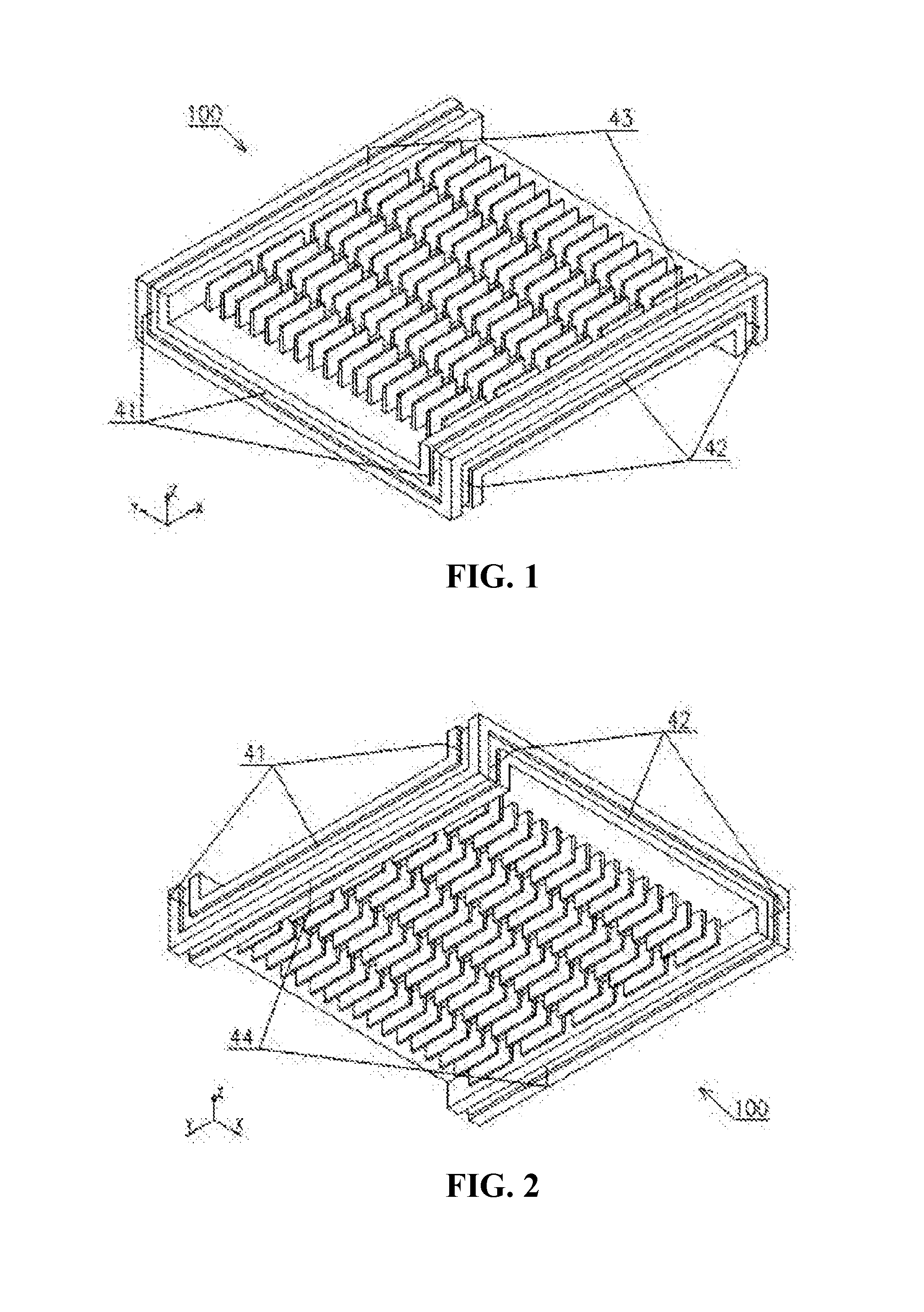
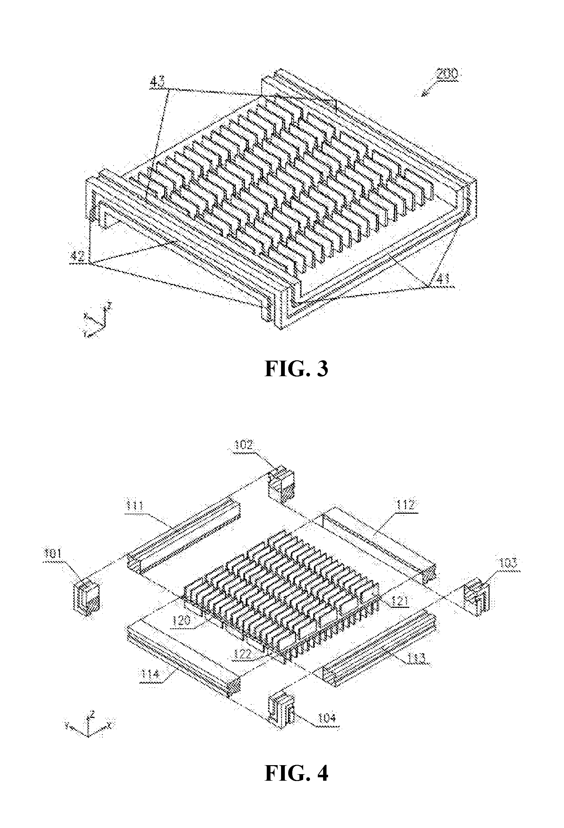
[0045]Referring to the drawings, a ceramic heat exchange plate is provided, including a central heat exchange plate 120 having a plurality of upper fins 121 and lower f...


PUM


Abstract

The present invention relates to a ceramic heat exchange plate and a ceramic heat exchange core assembled thereby. The ceramic heat exchange core comprises sealing strips, and the ceramic heat exchange plate. A plurality of ceramic heat exchange plates A and a plurality of ceramic heat exchange plates B are alternately superimposed. Side sealing strips are arranged inside top linear sealing grooves of the ceramic heat exchange plates A and bottom linear sealing grooves of the ceramic heat exchange plates B. Side sealing strips are arranged inside top linear sealing grooves of the ceramic heat exchange plates B and bottom linear sealing grooves of the ceramic heat exchange plates A. A plurality of ceramic heat exchange plates A, a plurality of ceramic heat exchange plates B and a plurality of sealing strips are assembled to form a ceramic heat exchange core. The ceramic heat exchange core is integrally sintered.

Description

TECHNICAL FIELD OF THE INVENTION[0001]The present invention relates to the technical field of industrial furnaces, in particular to a ceramic heat exchange plate used in flue gas waste heat recovery systems of various industrial furnaces and boilers, and a ceramic heat exchange core assembled thereby.BACKGROUND OF THE INVENTION[0002]An air pre-heater includes a heat exchange element made of ceramic material. The heat exchanger made of ceramic material has been applied. Such heat exchangers, having an applicable temperature generally up to 1400° C. are especially suitable for waste heat recovery from the high-temperature flue gas. Meanwhile, due to the corrosion resistance of the ceramic material, such heat exchangers are also suitable for waste heat recovery from the low-temperature flue gas. The technical status is as shown in the following publications:[0003]U.S. Pat. No. 4,681,157, titled “Crossflow Heat Exchanger”;[0004]U.S. Pat. No. 4,083,400, titled “Heat Recuperative Apparatu...

Claims


Application Information

Patent Timeline
IPC IPC(8): F28D21/00F28F21/04F28F3/10F28D9/00F28F3/04
CPCF28D21/001F28D9/0037F28F21/04F28F3/10F28F3/04F24H9/0084F28D9/02F28F3/048
Inventor WANG, FENGZEZHANG, XINYUXIA, ZHONGYUZHANG, YU
Owner CAS SUPER ENERGY TECH JINGJIANG
Why Eureka
Try Eureka