

Linear light guide, linear light guide structure, planar light guide structure, and illuminating device
a linear light guide and light guide body technology, applied in the direction of fibre light guides, instruments, transportation and packaging, etc., can solve the problems of difficult to increase the illumination intensity of the whole device, and the difficulty of using a long linear light guide body with a desired illumination intensity kep
- Summary
- Abstract
- Description
- Claims
- Application Information
AI Technical Summary
Benefits of technology
Problems solved by technology
Method used
Image

Examples
first embodiment
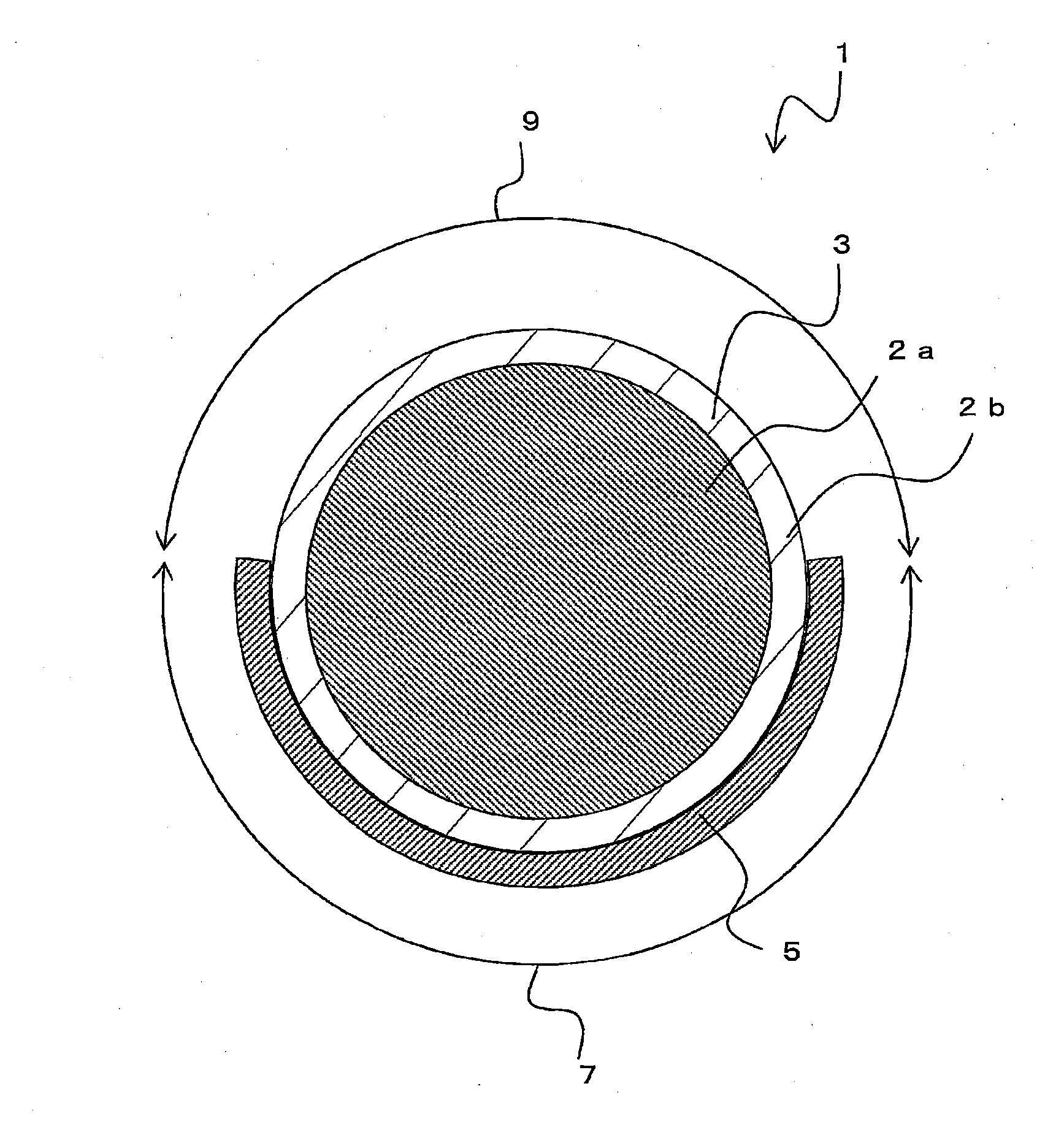
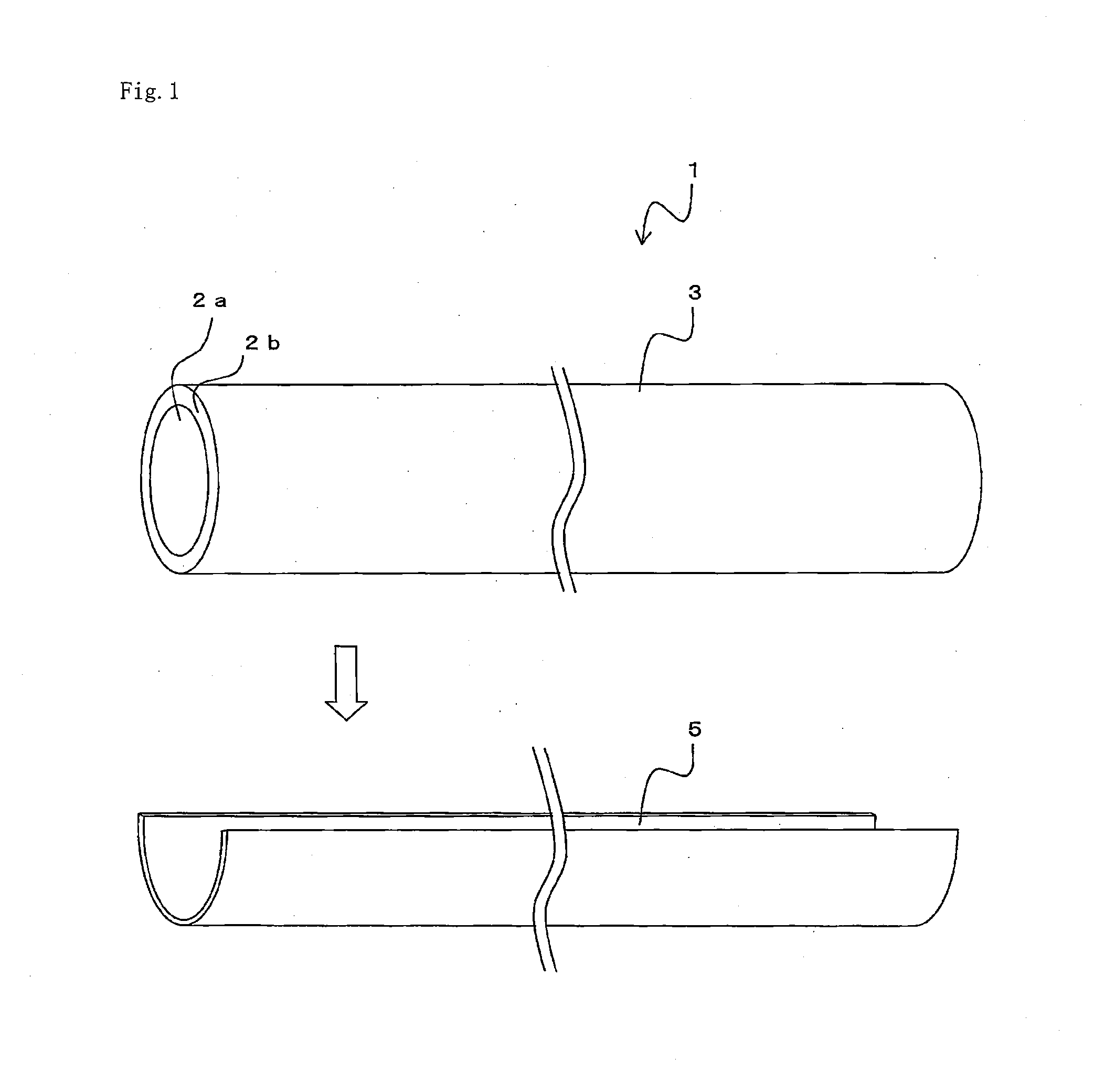
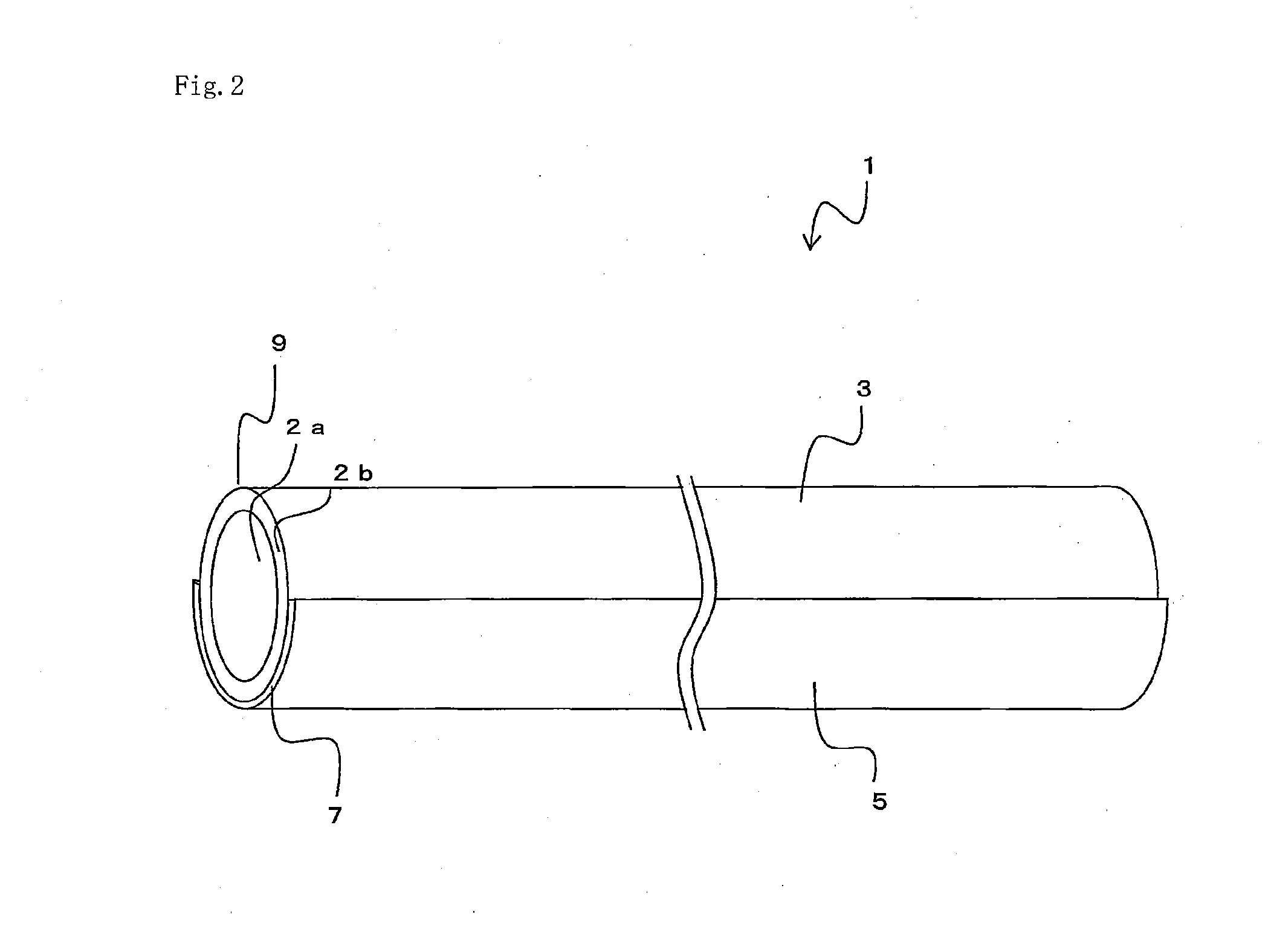
[0078]Hereunder is a description on a linear light guide 1 according to an embodiment. FIG. 1 is an exploded perspective view of the linear light guide 1, FIG. 2 is an assembly perspective view of the linear light guide 1, and FIG. 3 is a cross-sectional view vertical to a longitudinal direction of the linear light guide 1.
[0079]The linear light guide 1 is mainly made up of side emission type optical fiber 3, a flexible resin sheet 5, etc. The side emission type optical fiber 3 is flexible and allows light entering a core 2a to be radiated from a lateral side via a clad 2b.
[0080]As the side emission type optical fiber 3, a side emission type plastic optical fiber can be used which is optical fiber for transmitting visible light over a short distance, inexpensive, thick in core diameter, easy to be connected with a device that should be connected with the optical fiber, and comparatively light for its diameter. In this instance, as a core material, polymethylmethacrylate resin (PMMA...
second embodiment
[0126]Next is a description on a second embodiment. FIG. 4(a) is a cross-sectional conceptual view of a linear light guide 1a according to the second embodiment. In addition, in the following description, symbols the same as those in FIG. 1 to FIG. 3 are attached to structures exerting functions the same as those of the linear light guide 1, and thereby overlapping descriptions are omitted.
[0127]Side Emission Type Multi-Core Optical Fiber
[0128]A linear light guide 1a has a structure approximately the same as that of the linear light guide 1. The structure of the linear light guide 1a is, however, different in that side emission type multi-core optical fiber is used as the side emission type optical fiber. As the side emission type multi-core optical fiber, though the side emission type multi-core silica glass optical fiber can be used, the side emission type multi-core plastic optical fiber is preferable.
[0129]As the multi-core plastic optical fiber, side emission type multi-core pl...
third embodiment
[0138]Next is a description on a third embodiment. FIG. 5 is a perspective view of a linear light guide 1c according to the third embodiment. The linear light guide 1c has a structure approximately the same as that of the linear light guide 1. The linear light guide 1c is, however, different from the linear light guide 1 in that the flexible resin sheet 5 is spirally wound around the outer circumference of the side emission type optical fiber 3.
[0139]The flexible resin sheet 5 is spirally wound around the outer circumferential surface of the side emission type optical fiber 3 so as to form gaps at predetermined intervals on the outer circumferential surface of the side emission type optical fiber 3. Accordingly, the covered section 7 and the opened section 9 are spirally formed on the outer circumferential surface of the side emission type optical fiber 3. In addition, the covered section 7 and the opened section 9 are spirally and continuously formed in the longitudinal direction o...
PUM
| Property | Measurement | Unit |
|---|---|---|
| Length | aaaaa | aaaaa |
| Flexibility | aaaaa | aaaaa |
| Transparency | aaaaa | aaaaa |
Abstract
Description
Claims
Application Information