Display panel, driving method thereof and display device

a technology of display panel and driving method, applied in the field of display, can solve the problems of image display effect and touch sensitivity, and achieve the effect of good image display effect and higher touch sensitivity

Active Publication Date: 2016-10-13
BOE TECH GRP CO LTD +1
View PDF0 Cites 31 Cited by
  • Summary
  • Abstract
  • Description
  • Claims
  • Application Information

AI Technical Summary

Benefits of technology

[0022]The present invention has the following beneficial effects: in the display panel provided by the present invention, without adding a process step, by performing rectangular segmentation on the original plate-shaped common electrodes, it is ensured that common electrodes used during display and driving electrodes used during touch are electrically isolated from each other; in addition, he driving electrodes are connected by redundant data lines, the requirements for a touch function and a display function can be met simultaneously, and a display device comprising the display panel has a good image display effect and a higher touch sensitivity.

Problems solved by technology

However, the arrangement manner of the sensing electrodes Rx and the driving electrodes Tx commonly adopted at present is likely to cause too large coupling capacitance therebetween and thus affect the touch sensitivity.
Therefore, how to improve touch sensitivity and improve image display effect has become a technical problem to be urgently solved at present.

Method used


Image

  • Display panel, driving method thereof and display device
  • Display panel, driving method thereof and display device
  • Display panel, driving method thereof and display device

Examples


Embodiment Construction

[0032]The specific implementations of the present invention will be described in details below with conjunction with the drawings. It should be understood that the specific implementations described herein are merely for describing and explaining the present invention rather than limiting the present invention.

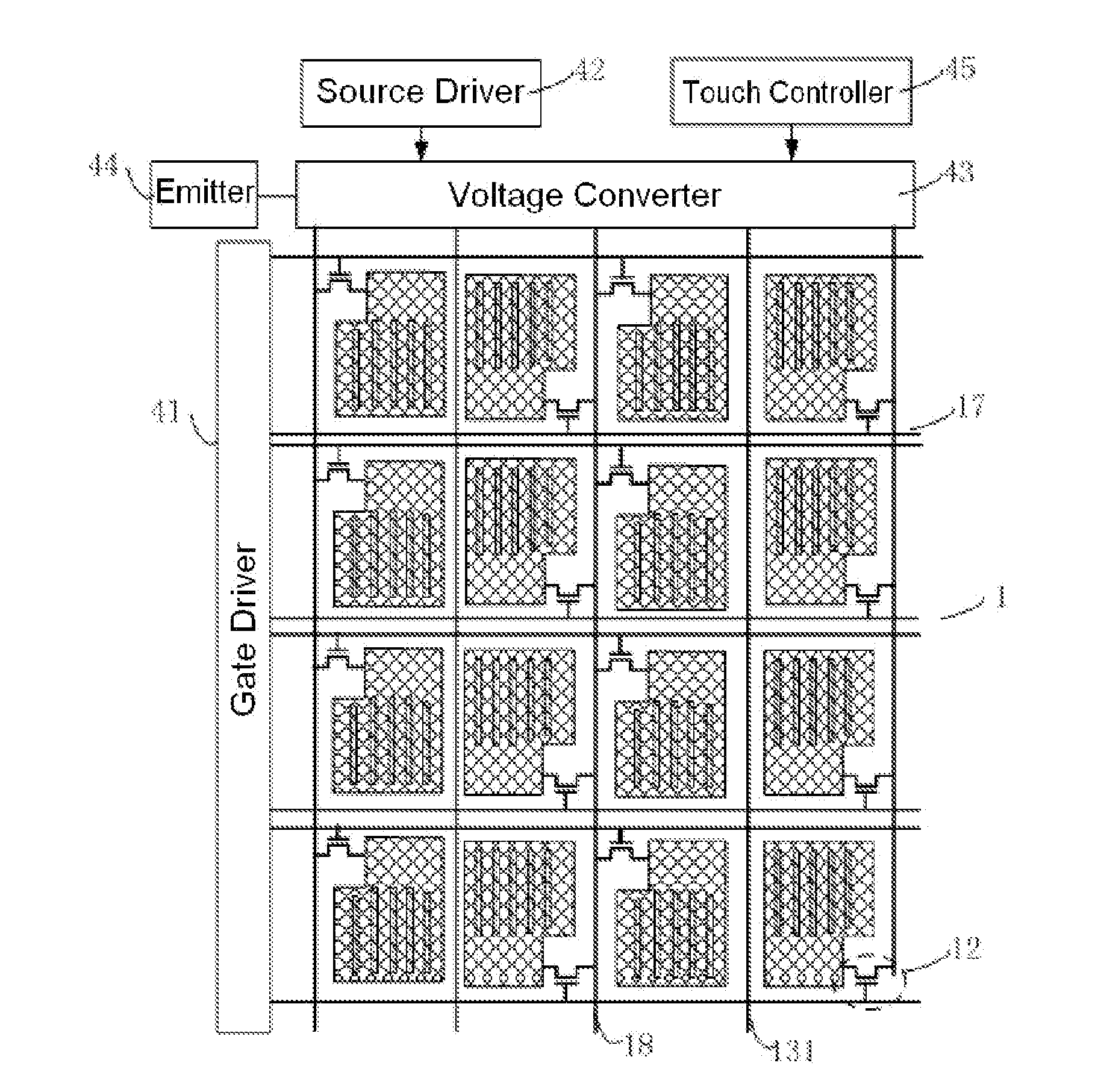
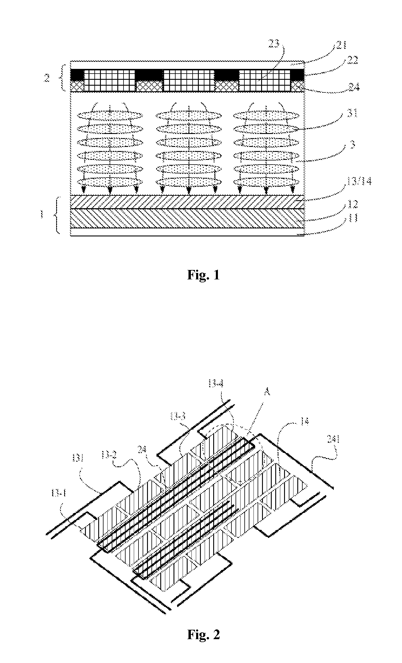
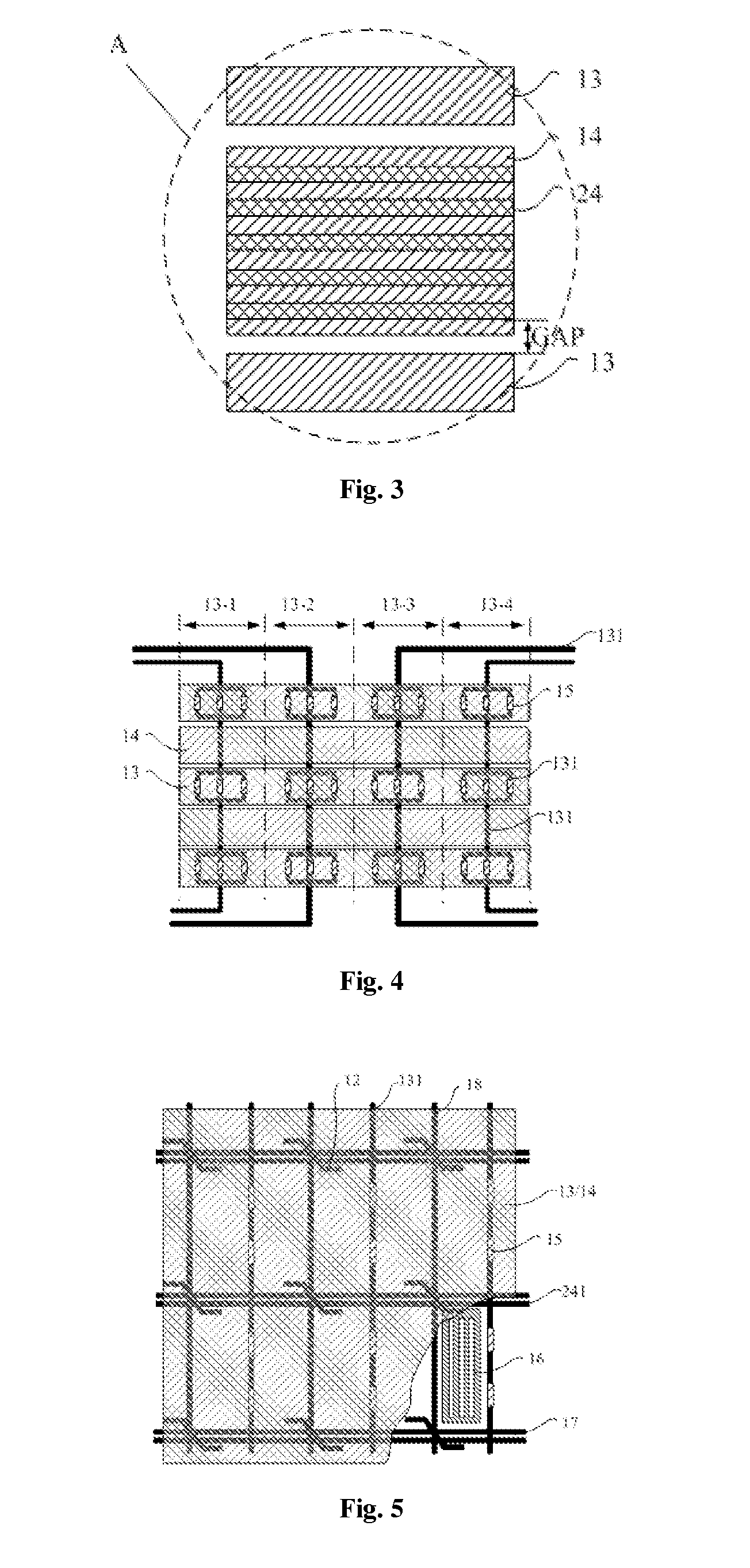
[0033]According to one aspect of the present invention, there is provided a display panel, including an array substrate and a color filter substrate, wherein the array substrate is provided with first electrodes and second electrodes, the color filter substrate is provided with third electrodes, the first electrodes and the second electrodes are arranged in a same layer, the first electrodes and the second electrodes are alternately arranged at intervals and electrically isolated from each other, and the second electrodes and the third electrodes are correspondingly arranged in space.

[0034]According to another aspect of the present invention, there is provided a display device...


PUM

PropertyMeasurementUnit
DC voltageaaaaaaaaaa
frequencyaaaaaaaaaa
widthaaaaaaaaaa

Abstract

The present invention relates to the field of display, particularly to a display panel, a driving method thereof and a display device. The display panel comprises an array substrate provided with first electrodes and second electrode arranged in a same layer and a color filter substrate provided with third electrodes. The first electrodes and the second electrodes are alternately arranged in parallel at intervals and electrically isolated from each other. The second electrodes and the third electrodes are arranged correspondingly in space. The present invention has the following beneficial effects: by performing rectangular segmentation on the original plate-shaped common electrodes, the display panel ensures that common electrodes during display and driving electrodes during touch are electrically isolated from each other; in addition, as the diving electrodes are connected by redundant data lines, a display device comprising the display panel has a good image display effect and a higher touch sensitivity.

Description

FIELD OF THE INVENTION[0001]The present invention relates to the field of display, in particular to a display panel, a driving method thereof, and a display device including the display panel.BACKGROUND OF THE INVENTION[0002]A touch panel, as the latest information input equipment at present, can realize human-machine interaction easily, conveniently and naturally and provides a new multimedia human-machine interaction mode for people. Due to the advantages of sensitive touch response, supporting multi-point touch and the like, the touch panel greatly meets people's visual and tactile enjoyment.[0003]Generally, a touch panel at least includes a display panel for displaying and a touch panel for touching. At present, touch panels may be classified into add on mode touch panels, on cell touch panels and in cell touch panels according to the structures thereof. In other words, sensing electrodes Rx and driving electrodes Tx are formed inside or outside or on a surface of the display pa...

Claims


Application Information

Patent Timeline
Patent Type & Authority Applications(United States)
IPC IPC(8): G06F3/041G09G3/36G02F1/1362G06F3/044
CPCG06F3/0416G06F3/044G09G3/3655G02F1/136286G09G2300/0426G06F3/0412G09G2310/0278G09G2300/0809G02F1/136209G02F1/13338G09G3/3648G09G2354/00G06F3/04166G06F3/0445
Inventor YANG, SHENGJIDONG, XUEWANG, HAISHENGWANG, LEIWANG, CHUNLEILIU, YINGMINGXIE, XIAOBO
Owner BOE TECH GRP CO LTD
Why Eureka
Try Eureka