Electro hot spot vending machine

Active Publication Date: 2016-10-13
JONES CHARLIE ELLIS
View PDF8 Cites 11 Cited by
  • Summary
  • Abstract
  • Description
  • Claims
  • Application Information

AI Technical Summary

Benefits of technology

[0030]The instant invention is an electrical distribution box that includes a uniquely-shaped metal housing and which distributes electricity to an electrical outlet or charging cord only after the user has prepaid for a selected amount the electricity. The user is allowed to access metered electricity through a receptacle arranged within the distribution box. The user is allowed to connect a device or power cord to the internally arranged power receptacle. Electricity is thereafter distributed through the outlet via the power cord for the preselected amount of time. The receptacle connects to a power source via a timer switch which controls

Problems solved by technology

However, with the continued reduction of coal usage in the production of electricity, the cost of electricity is rapidly increasing.
Such cost increases tend to push the budget of fixed-income families, which may result in these families being driven from the electricity marketplace because they are unable to pay a monthly electric bill.
This tends to inconvenience othe

Method used


Image

  • Electro hot spot vending machine
  • Electro hot spot vending machine
  • Electro hot spot vending machine

Examples


first embodiment

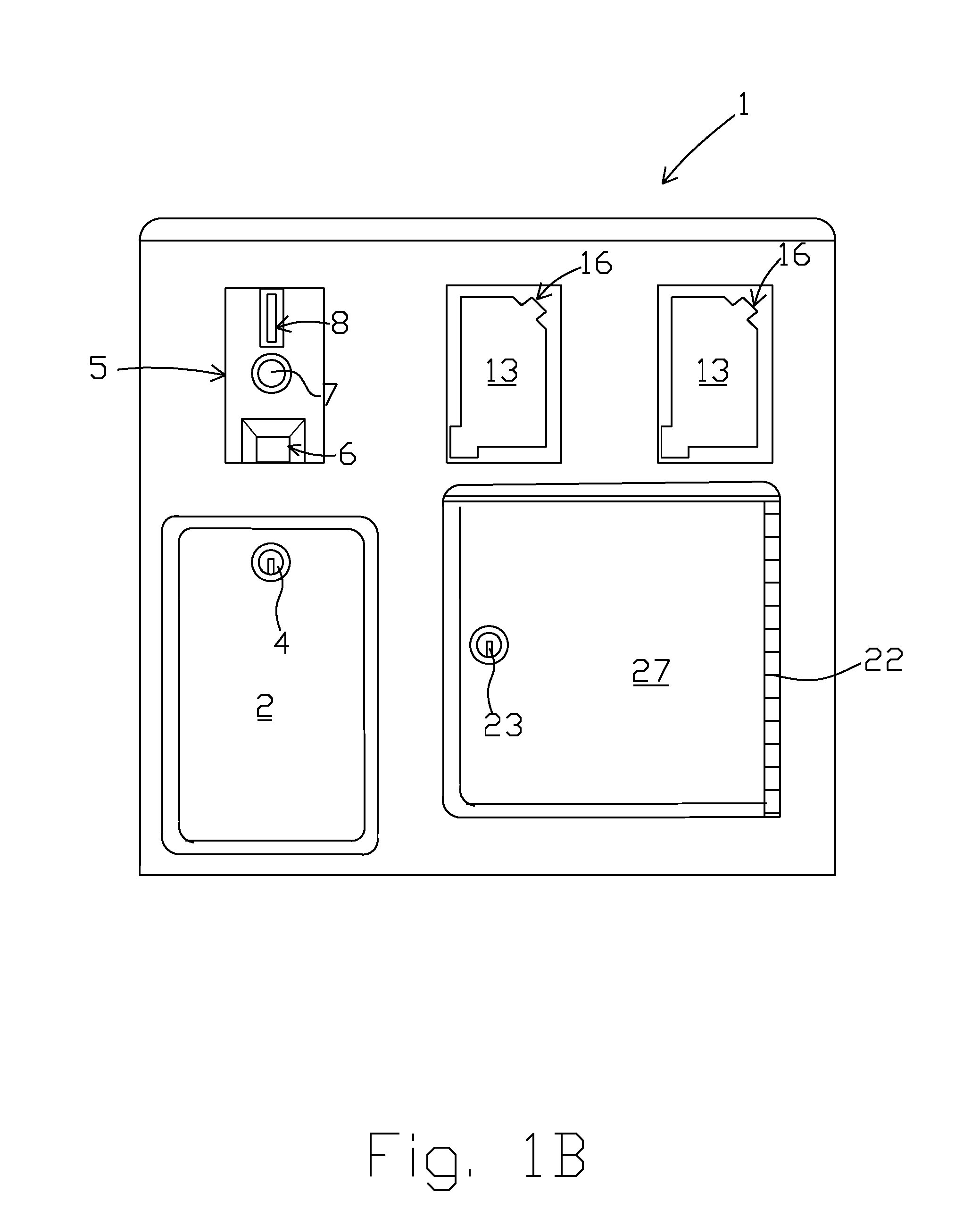
[0041]In the first embodiment, as represented by FIGS. 1A-1G, the invention comprises a vending machine from which electricity is sold. The vending machine 1 includes a front side of an outer casing or housing 10 that includes a coin acceptor 5, a pair of timed receptacles 39 covered by respective weather proof covers 13, a coin retrieval door 2 that opens into a currency storage recess 3, and a security locker door 27 which opens into a recess that forms a security locker 28 which allows cellular telephones and other small hand-held devices to be deposited and left unattended during a charging operation. The security locker door 27 is fastened to the front side of the outer casing via a hinge 22. A keyed-lock 23 is provided along a side of the security locker door 27 opposite the hinge 22. The weather proof receptacle covers 13 are mounted in openings 40 and coupled to the front side 1 via respective spring-loaded hinges 16. The receptacles 39 are protected by ground fault circuit ...

third embodiment

[0050]FIG. 3 shows the machine. In this instance, the keypad includes an enter button and a cancel button along with buttons representative of numbers 1-9. The GFCI receptacles and their associated spring-loaded covers are provided above the keypad 60 along with a display 63 and the respective currency accepting devices 8, 64, 65.

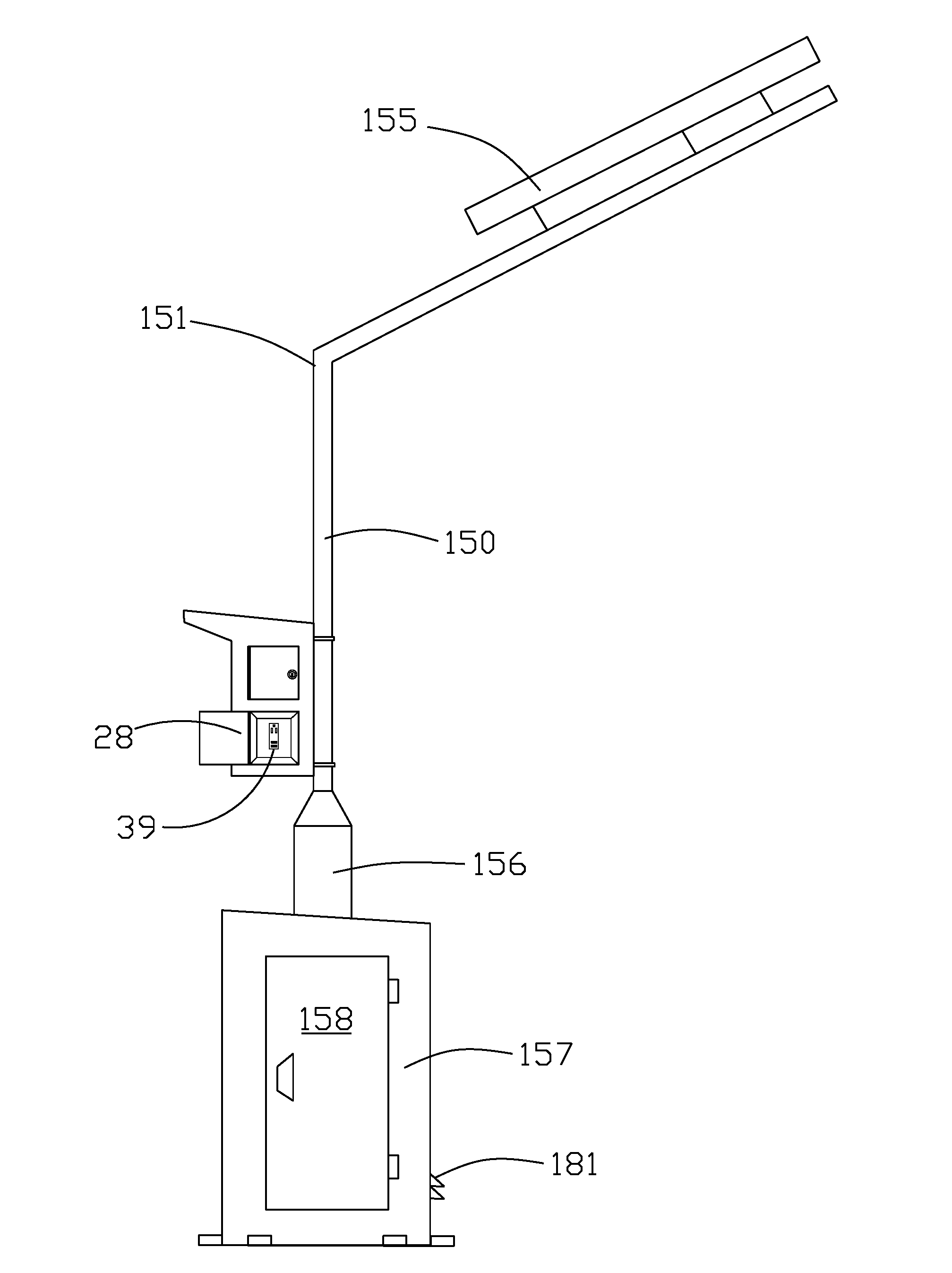
[0051]FIG. 4 is a representative schematic showing a solar panel 155 coupled to a charge controller 174 and a pair of batteries 175. The solar panel 155 charges the batteries during the daylight hours while the sun is shining after which the energy stored in the batteries are utilized when at night or during overcast days. It should noted that the solar panel may be substituted for another power source such as the electrical grid. Energy from the batteries is converted from DC to AC in inverter 173. Electricity from the inverter 173 is routed to a terminal bar or bus 172. A neutral is connected to a first set of terminals. A ground is coupled to another set...


PUM


Abstract

An electrical distribution center includes a plurality of electrical receptacles or ports which are activated when currency is deposited into a currency receiving mechanism that is coupled to a timer switch. Electricity is provided to the receptacles for a pre-paid period of time. Thereafter, the timer switch opens to prohibit further flow of electricity to the receptacles until additional currency is deposited or credited to the electrical distribution center. The electrical distribution center may be connected to an electrical grid or include an electricity generating source such as a solar panel and associated control circuitry.

Description

[0001]The present application relates to U.S. Provisional Patent Application Ser. No. 62 / 178,503 filed on Apr. 13, 2015 and claims priority therefrom.[0002]The present application was not subject to federal research and / or development funding.TECHNICAL FIELD[0003]Generally, the invention relates to an electrical distribution device comprising a plurality of receptacles for providing both alternating and direct current (AC / DC). Specifically, the invention is a vending machine that distributes metered electricity for use in powering small hand-held devices and / or charging electronic devices. Thus, the invention assists people that need a place to recharge their electrical devices. It should be noted that in the United States, electricity is traded or sold on the electrical grid in amounts of kilowatt / hours. In the present invention, metered electricity is to be sold in typical smaller increments of watts / minutes.BACKGROUND OF THE INVENTION[0004]Most households in the United States are...

Claims


Application Information

Patent Timeline
IPC IPC(8): G07F15/00G06Q50/06G07F9/04H04M17/02
CPCG07F15/006G07F9/04G06Q50/06H04M17/026G06Q20/145G07F15/003G07F15/005Y02T90/12
Inventor JONES, CHARLIE
Owner JONES CHARLIE ELLIS
Why Eureka
Try Eureka