
Antenna structure

Inactive Publication Date: 2016-10-13
NAT TAIWAN UNIV
View PDF0 Cites 0 Cited by
  • Summary
  • Abstract
  • Description
  • Claims
  • Application Information

AI Technical Summary

Benefits of technology

The present invention provides a solution by designing a built-in antenna structure that can be used in a wireless communication device with a full-metal back cover. This allows for better bandwidth and efficiency, while still maintaining a slim design and good appearance. The problem of limited bandwidth and poor radiation performance due to the full-metal back cover is solved with this innovation.

Problems solved by technology

However, due to the effect of the design of a full-metal back cover, the radiation feature of an antenna is often affected by the metal shielding effect, which results in low bandwidth and radiation efficiency or even a dead angle during signal transmission.
However, this method greatly affects the appearance of a product.

Method used


Image

  • Antenna structure
  • Antenna structure
  • Antenna structure

Examples


Embodiment Construction

[0022]The present invention may be fully understood according to the description of the following embodiments, so that a person skilled in the art can implement the present invention according to the description. However, implementation of the present invention is not limited to implementation forms of the following embodiments. Same reference numerals always present same components.

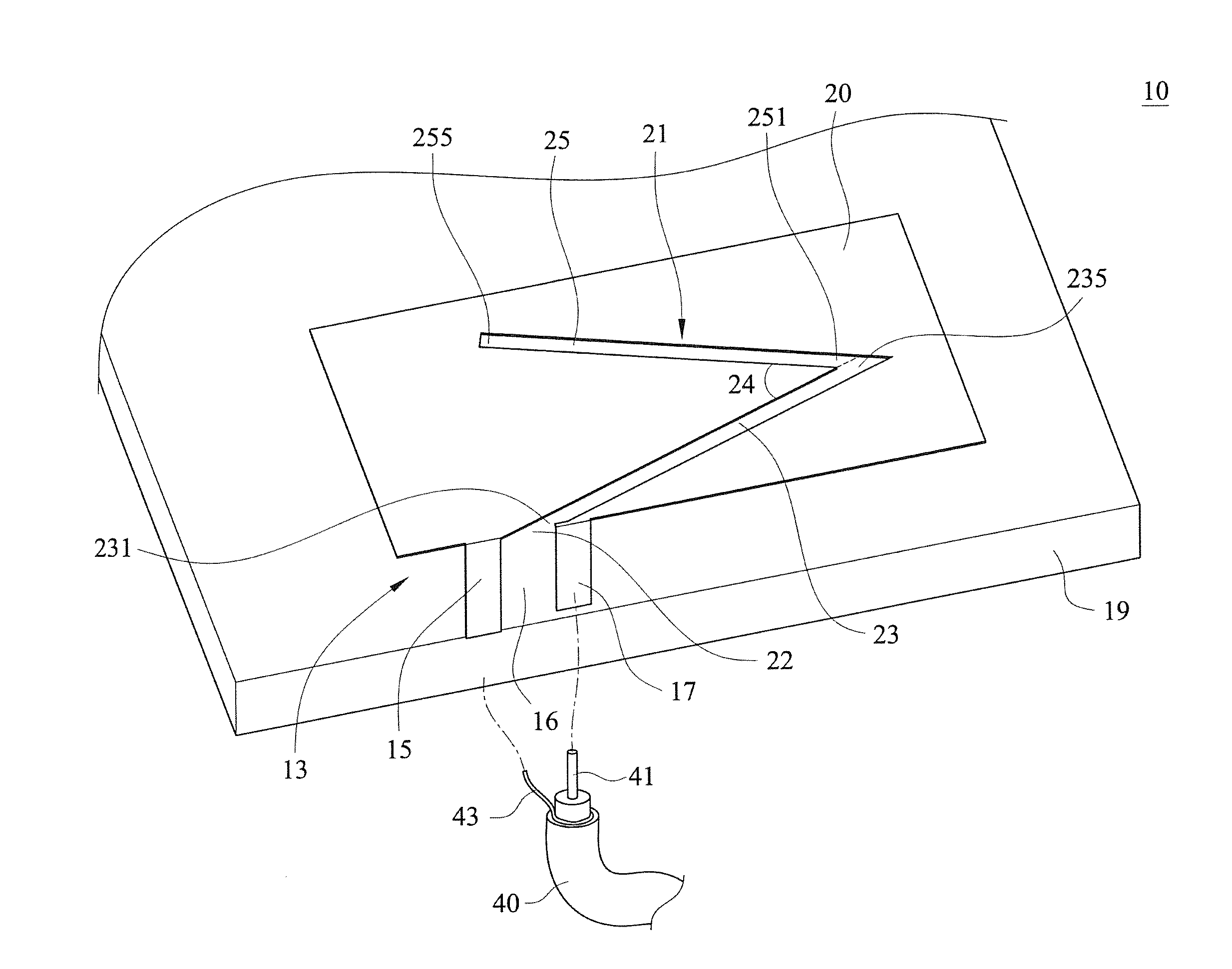
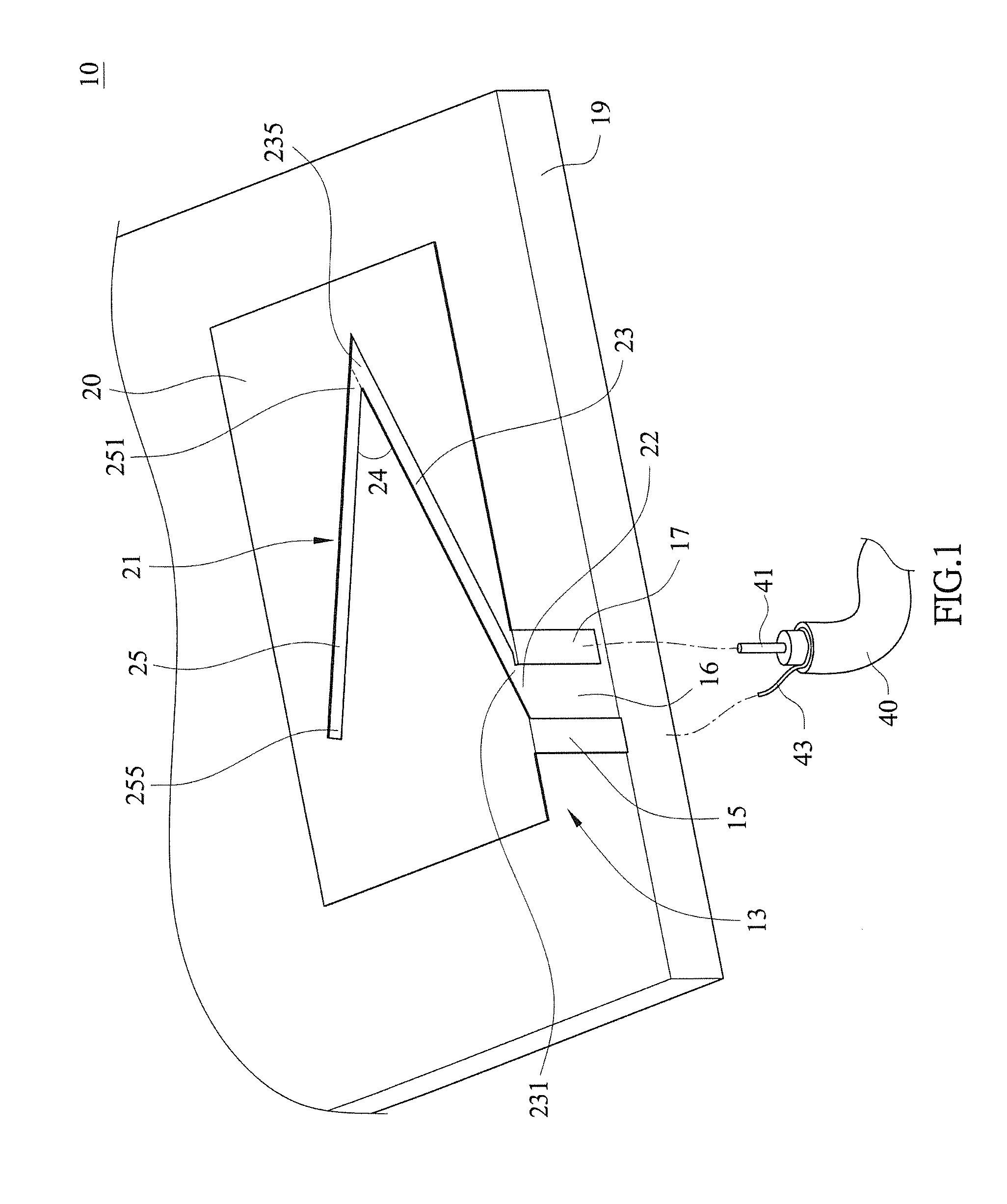
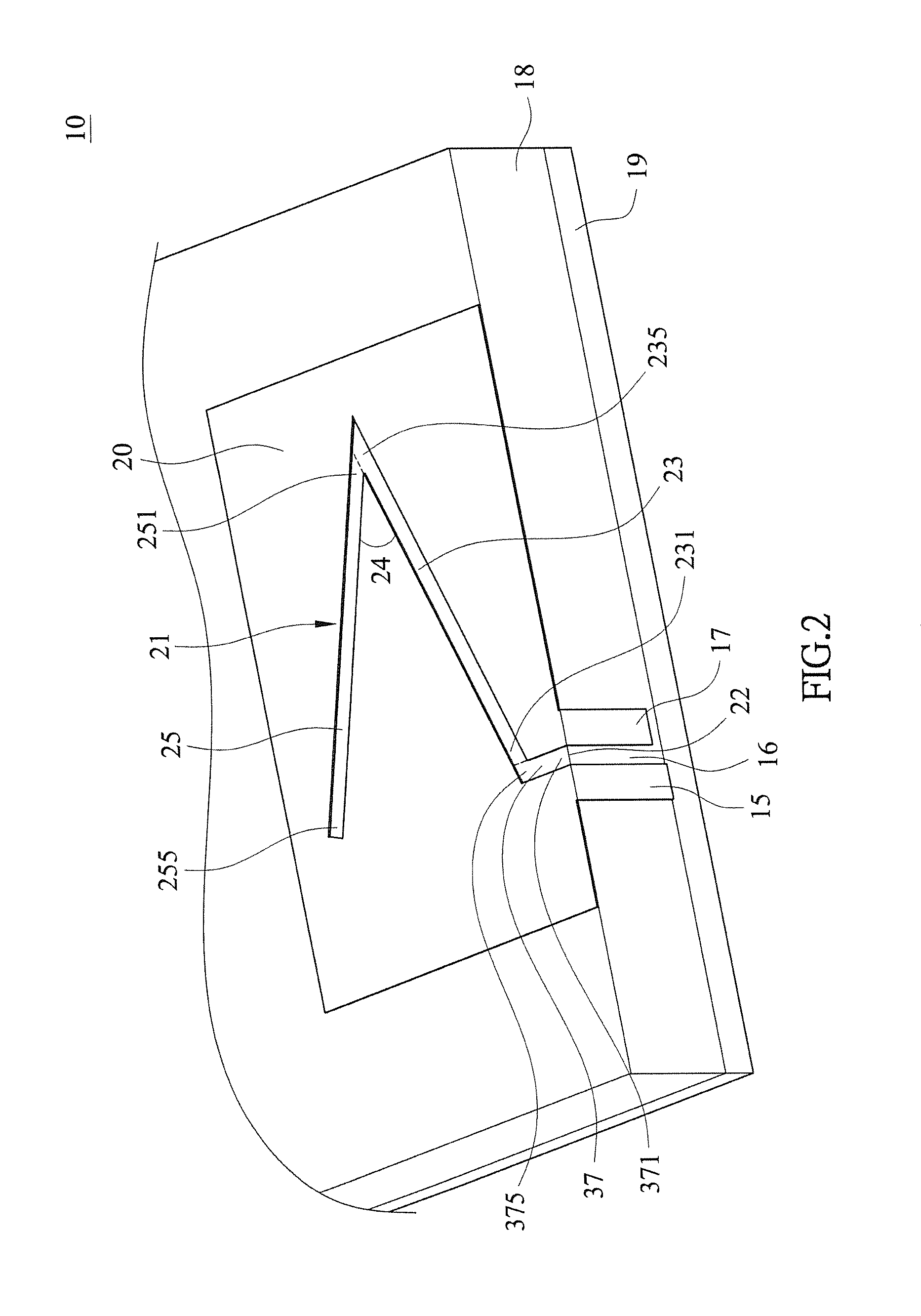
[0023]First, referring to FIG. 1, a schematic structural diagram of an embodiment of an antenna structure according to the present invention is shown. As shown in the drawing, an antenna 10 includes a metal radiation plate 20, a slot 21, a connecting grounding plate 15, a feed plate 17, and a metal grounding plate 19.

[0024]The metal radiation plate 20 has a slot 21 and a starting end 22, where the starting end 22 is located on an edge of the metal radiation plate 20, the slot 21 extending laterally has a first slot part 23 and a second slot part 25, two ends of the first slot part 23 can be defined as a ...


PUM


Abstract

The present invention provides an antenna structure, using a metal radiation plate having at least one bending slot and a metal grounding plate, where a starting end of the metal radiation plate is located on an edge of the metal radiation plate. A feed plate and a connecting grounding plate are separately connected to two sides of a starting end of the slot, and two ends of the connecting grounding plate may be separately connected to the metal radiation plate and the metal grounding plate. The feed plate may be connected to a core wire of a coaxial cable, and a peripheral conductor of the coaxial cable is connected to the metal grounding plate, so that different resonant modes can be controlled. The antenna can achieve a broadband effect, thereby solving the problem of the metal shielding effect in a wireless communication product using a full-metal back cover.

Description

BACKGROUND[0001]1. Technical Field[0002]The present invention relates to an antenna structure, and in particular, to an antenna structure applied to a wireless communication product with a full-metal back cover.[0003]2. Related Art[0004]A conventional wireless communication product often requires the design of a full-metal back cover, so as to support structural strength, show the metallic texture, and improve appearance. Based on the consideration of the appearance of a product, most antennas are designed to be built-in. However, due to the effect of the design of a full-metal back cover, the radiation feature of an antenna is often affected by the metal shielding effect, which results in low bandwidth and radiation efficiency or even a dead angle during signal transmission. In order to solve the problem in the radiation feature of an antenna during transmission, a conventional structure requires cutting a section of metal from the full-metal back cover and filling the section with...

Claims


Application Information

Patent Timeline
IPC IPC(8): H01Q13/16H01Q13/10
CPCH01Q13/106H01Q13/16H01Q9/0421H01Q9/0442
Inventor WU, TZONG-LINCHOU, JUI-HUNGCHANG, JO-FANLIN, DING-BING
Owner NAT TAIWAN UNIV
Learn More