De-Icing Splitter Lip for Axial Turbomachine Compressor

a splitter and compressor technology, applied in the direction of machines/engines, mechanical equipment, sustainable transportation, etc., can solve the problems of ice formation on the lip, block detachment, and ice accumulation on the lip,

Active Publication Date: 2016-10-20
TECHSPACE AERO
View PDF3 Cites 3 Cited by
  • Summary
  • Abstract
  • Description
  • Claims
  • Application Information

AI Technical Summary

Problems solved by technology

Since these temperatures can drop to −50° C. at altitude, humidity can cause ice to form on the lip.
These blocks can also alter the shape of the lip and influence the air flow entering the compressor, which can impair the performance of the latter.
As they develop, the blocks can become particularly large and then detach due to the vibrations of the turbomachine.
The incoming flow can cause these blocks to be ingested by the compressor, with the concomitant risk of damage to the rotor blades.
This ingestion is particularly harmful as it does not pass through the fan beforehand.
This means that thermal conduction between the lip and the pipes is not optimal, resulting in impaired de-icing.

Method used


Image

  • De-Icing Splitter Lip for Axial Turbomachine Compressor
  • De-Icing Splitter Lip for Axial Turbomachine Compressor
  • De-Icing Splitter Lip for Axial Turbomachine Compressor

Examples


first embodiment

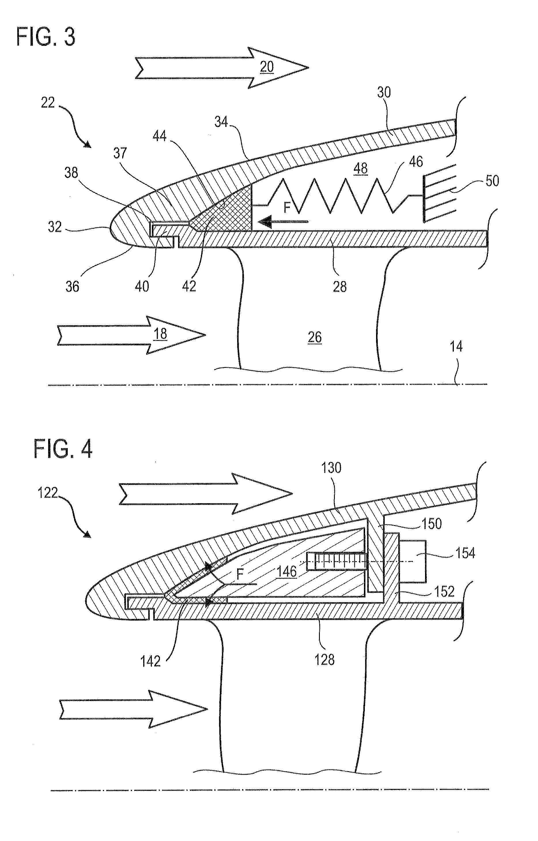
[0058]FIG. 3 shows a splitter lip 22 according to the present application. It serves to split the primary flow 18 and the secondary flow 20; the axis of rotation 14 is provided by way of reference.

[0059]The splitter wall 30 is annular with a profile of revolution and serves to divide at least one annular flow from the flow entering the turbomachine. In this case, it separates the primary flow18 and the secondary flow 20 by means of its circular leading edge 32. The splitter wall 30 has an outer splitter surface 34 in contact with the secondary flow 20 and an inner splitter surface 36 in contact with the primary flow 18. These splitter surfaces meet at the leading edge 32.

[0060]The splitter wall 30 has an upstream thickened portion 37 on which the leading edge 32 is formed. It also has an annular attachment slot 38 which serves for attaching the outer shroud 28. Moreover, the latter has an upstream annular hook 40 which is introduced into the attachment slot 38. The thickened portion...

third embodiment

[0069]FIG. 5 shows a splitter lip 222 according to the present application. This FIG. 5 repeats the numbering of the preceding figures for identical or similar elements, this numbering being however increased by 200. Specific numbers are used for the elements specific to this embodiment. The splitter wall 230 and the outer shroud may be generally identical to the preceding embodiments.

[0070]The heating device 242 may be identical to those described for FIG. 4. The elastic element 246 forms a strip inserted into the heating device 242. The splitter lip 222 comprises a wedge 256 positioned against the elastic element 246 and a downstream support, in this case the flange 250 of the splitter wall 230. The wedge 256 forms an annular spacer which provides a closer bearing surface. The thrust elements 254 may engage with the wedge 256 and remain remote from the elastic element 246. This lightens the lip 222.

[0071]During assembly of the splitter lip 222, the elastic element 246 is placed on...


PUM


Abstract

The present application relates to a de-icing splitter lip for a low-pressure compressor of a turbofan aircraft engine. The splitter lip surrounds the primary flow and includes an annular splitter wall with a circular leading edge, an outer shroud connected to the splitter wall, and a heating device in an electric ribbon that de-ices the splitter lip. The splitter lip further includes an elastic element made of elastomer, holding the heating device on the inside of the splitter wall. The elastic element is compressed, pre-loaded, in the splitter lip. Thus, the elastic element exerts a force F clamping the heating device against the splitter wall and the outer shroud in order to improve thermal contact. The present application also provides a method for assembling a splitter lip.

Description

[0001]This application claims priority under 35 U.S.C. §119 to Belgium Patent Application No. 2015 / 5255, filed 20 Apr. 2015, titled “De-Icing Splitter Lip for Axial Turbomachine Compressor,” which is incorporated herein by reference for all purposes.BACKGROUND[0002]1. Field of the Application[0003]The present application relates to the field of turbomachine de-icing. More precisely, the present application deals with a splitter lip for an axial turbomachine. The present application also considers an axial turbomachine fitted with a de-icing splitter lip.[0004]2. Description of Related Art[0005]Turbofan engines have been developed to care for the environment. Care for the environment is in this case intended to mean limiting noise and reducing consumption. With a view to optimizing their thrust and performance while reducing noise, jet engines use multiple annular air flows. Generally, a turbomachine splits an incoming air flow into a primary flow and a secondary flow in the form of ...

Claims


Application Information

Patent Timeline
Patent Type & Authority Applications(United States)
IPC IPC(8): F02C7/047F02C3/04
CPCF02C7/047F05D2220/32F02C3/04F01D25/02F05D2230/60F05D2260/221F05D2260/38Y02T50/60
Inventor BOUILLON, DAVIDHERBAUT, GHISLAIN
Owner TECHSPACE AERO
Why Eureka
Try Eureka