System for detection of fluid pressure using a pressure sensing capacitive sensor

Inactive Publication Date: 2016-10-27
GUIDED INTERVENTIONS
View PDF0 Cites 10 Cited by
  • Summary
  • Abstract
  • Description
  • Claims
  • Application Information

AI Technical Summary

Benefits of technology

[0003]The present invention aims to optimize and facilitate in vivo fluid pressure measurements, for example, by performing FFR measurements with a small catheter advanced over a standard guide wire. More particularly, the present invention contemplates obtaining in vivo fluid pressure measurements by utilizing a catheter with just one electrical contact to be made to the measurement system. Therefore the catheter structure itself can be utilized to serve as an electrical conductor and no special or dedicated signal communication lines need to be integrated into the catheter, keeping the dimensions of the catheter to a minimum while optimizing handling characteristics. It is to be noted that the present invention also contemplates blood pressure measurement systems where a catheter is omitted. Where a catheter is included in the system, the sensor is incorporated into the wall of the catheter. Where a solid wire is provided which extends parallel to a steering guide wire, the sensor may be integrated into the solid wire. In one embodiment, the present invention is directed to a FFR catheter system utilizing a standard or off-the-shelf guide wire. The catheter has a distal portion with a capacitive sensor. The capacitive sensor is either an electrolytic sensor (a capacitor with an e

Problems solved by technology

This is an improvement over a cable connection, however, still very cumbersome, since for every catheter insertion the connector handle needs to be disconnected from the proximal wire end before the catheter can be advanced over the wire.
Also, these FFR wires are complex in structure since special auxiliary signal

Method used


Image

  • System for detection of fluid pressure using a pressure sensing capacitive sensor
  • System for detection of fluid pressure using a pressure sensing capacitive sensor
  • System for detection of fluid pressure using a pressure sensing capacitive sensor

Examples


Embodiment Construction

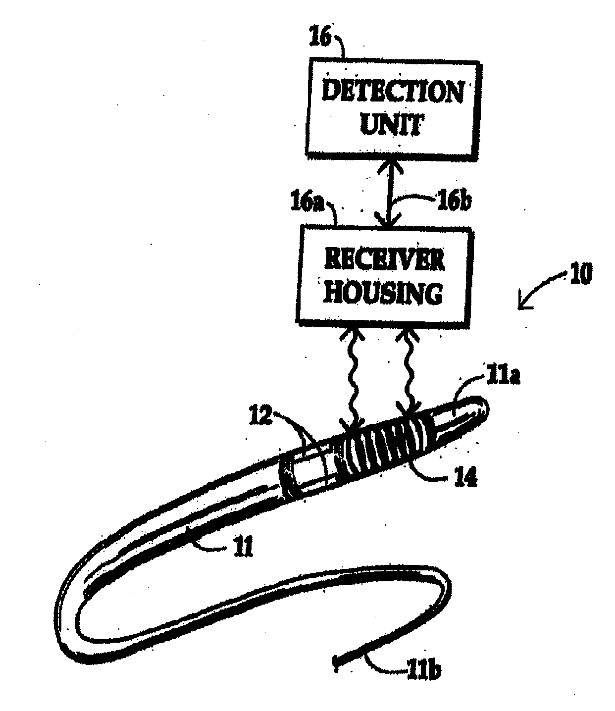
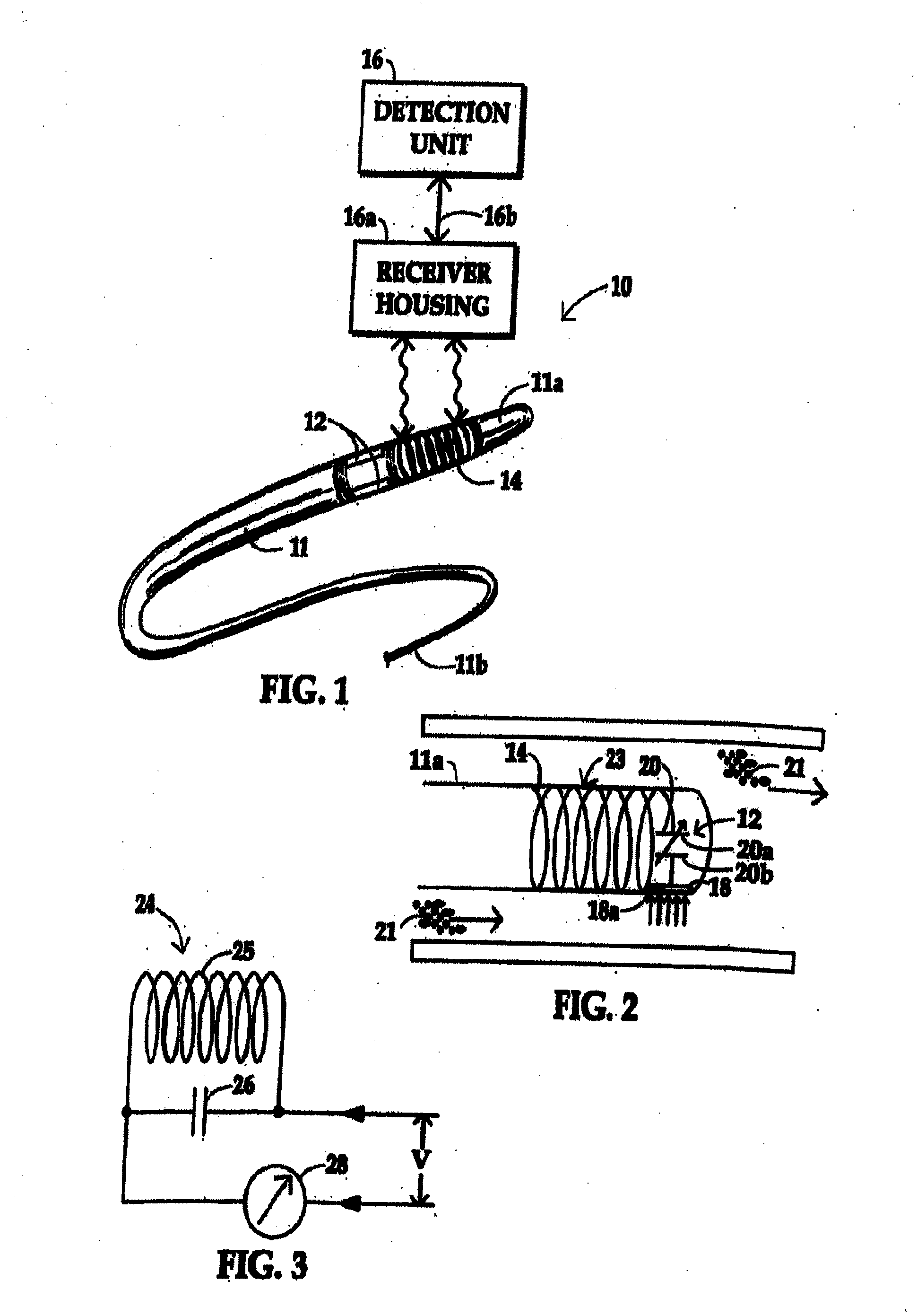
[0061]FIGS. 1-46 and the associated description thereof hereinafter are directed to a pressure sensing system where a sensor is incorporated in an interventional medical guide wire. Pursuant to FIGS. 47AS through 53, a pressure sensor may be provided in a catheter, imbedded in the catheter wall, or in an elongate shaft that extends in parallel to an introducing guide wire.

[0062]As illustrated in FIG. 1, a pressure sensing guide wire system 10 comprises a guide wire 11 having a sensor 12 and coil 14 at its distal end portion 11a. FIG. 5 shows the mechanical arrangement of a floppy tip coil 14 and a capacitive sensor 20 forming a pressure sensing resonance circuit. The guide wire 11 may be inserted into the cardiovascular system of a patient. Small flexible devices, called catheters, may be guided over the guide wire 11 inserted through blood vessels and vascular structures of the patient, such as to the site of a damaged or diseased blood vessel, as typically performed in interventio...


PUM


Abstract

A system having a catheter having a distal pressure sensitive capacitive element providing an impedance and phase shift which varies responsive to the amount of pressure from blood external the catheter, a detector having electronics for determining the impedance and/or phase shift. This impedance and or phase shift corresponds to the pressure of the blood about the distal end of the catheter. When the catheter is inserted into a patient's body, the impedance or phase shift is detected quasi wirelessly without special signal communication means like optical fibers or electrical wires from outside the patient's body utilizing the patient as a ground path and the catheter shaft as an electrical conductor.

Description

FIELD OF THE INVENTION[0001]The present invention is related to a system (apparatus and method) for detection of fluid pressure, such as blood pressure in a blood vessel. The invention is directed in part to a system having a catheter with a sensor for sensing pressure of the blood, and a method using same for monitoring the blood pressure sensed.BACKGROUND OF THE INVENTION[0002]Interventional cardiologists rely on guide wires to reach the treatment site inside a blood vessel, such as the coronary arteries. Instead of utilizing the guide wire as a strictly mechanical- or guiding-tool, pressure and flow wires are being promoted as a dual function guide wires, providing mechanical guidance and hemodynamic information at the same time. Based on the results of the FAME and DEFER studies (see Pijls et al. “Percutaneous Coronary Intervention of Functionally Nonsignificant Stenosis 5 Year Follow Up of the DEFER Study”. J Am Coll Cardiol 2007 vol 49 (21) pp 2105-2111), FFR (Fractional Flow ...

Claims


Application Information

Patent Timeline
IPC IPC(8): A61B5/0215A61B5/00
CPCA61B5/0215A61B5/7257A61B5/0022A61B5/6851A61B5/6852A61B2562/0214G01L9/0073
Inventor WARNKING, REINHARDSCHULZE-CLEWING, JOERGDIPAOLA, DAVIDSHIN, DONG LKPOLLMAN, MATTHEW J.
Owner GUIDED INTERVENTIONS
Why Eureka
Try Eureka