
Management and utilization of fault domains in distributed cache systems

a distributed cache and fault domain technology, applied in the field of distributed cache data systems, can solve the problems of loss of data replication advantages, difficulty in cache and retrieval data quickly and accurately,

Active Publication Date: 2016-10-27
PERNIXDATA
View PDF14 Cites 5 Cited by
  • Summary
  • Abstract
  • Description
  • Claims
  • Application Information

AI Technical Summary

Benefits of technology

The patent describes a method for data replication in a cluster of computer systems. The method involves a computing system obtaining a default fault domain configuration, and then detecting and specifying the occurrence of an operating fault. The computing system then reconfigures the host configuration for data replication based on the new fault domain system configuration, and data replication is performed based on the reconfigured specification of which hosts to use for data replication. The method allows for efficient and effective data replication in a cluster configuration.

Problems solved by technology

As an example, many modern microprocessors incorporate an instruction cache holding a number of instructions; when the microprocessor executes a program loop where the same set of instructions are executed repeatedly, these instructions are fetched from the instruction cache, rather than from an external memory device at a performance penalty of an order of magnitude or more.
While various write-through and write-back caching algorithms exist, caching and retrieving data quickly and accurately remains a challenge.
However, the advantages of replication can be lost when the replication occurs on the same physical machine.
The advantages of data replication can also be lost when the replication occurs to a different physical machine that would be equally impacted by a fault affecting the machine from which the data was copied.
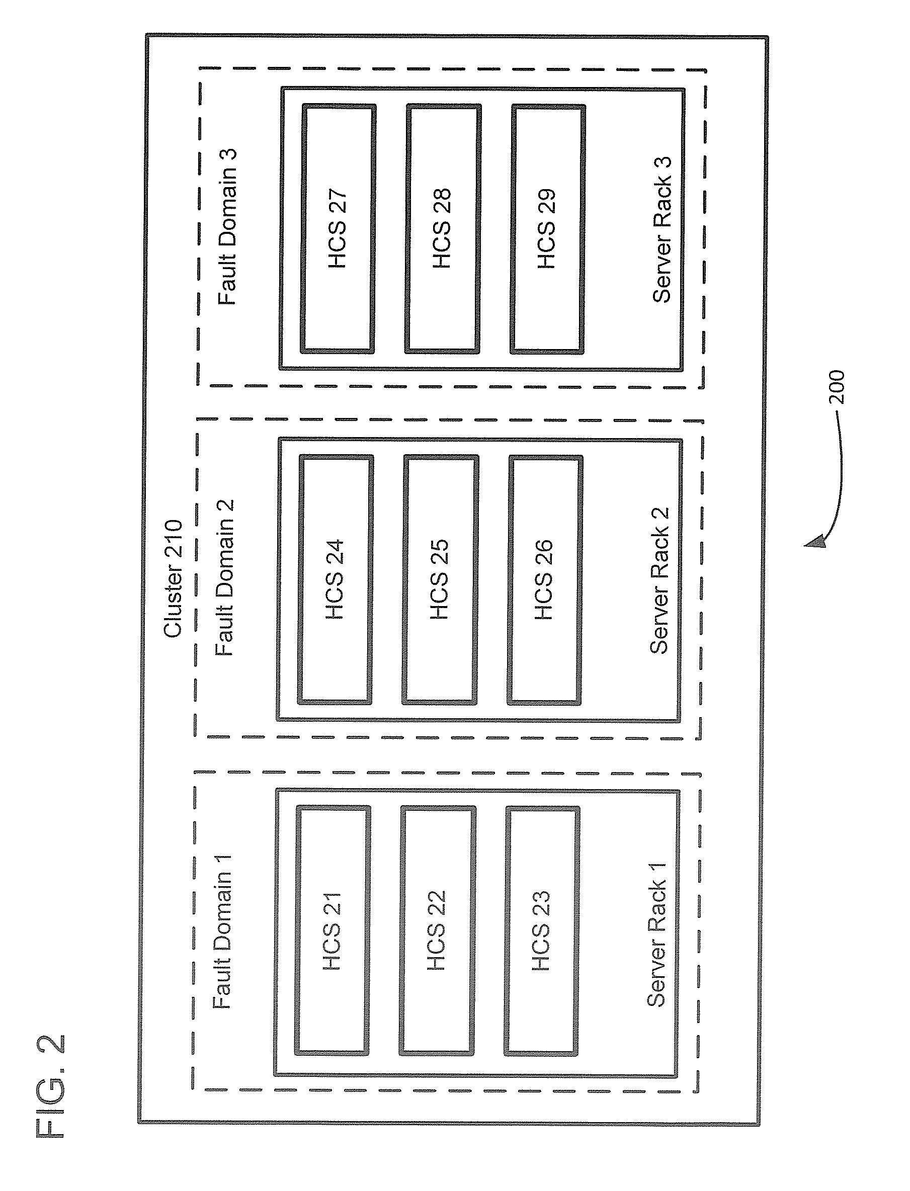
For example, if both machines were in the same server rack then a power failure to that rack would affect both machines.
As another example, if both machines were in the same data center and some disaster occurred at that data center then both machines would be affected.

Method used


Image

  • Management and utilization of fault domains in distributed cache systems
  • Management and utilization of fault domains in distributed cache systems
  • Management and utilization of fault domains in distributed cache systems

Examples


Embodiment Construction

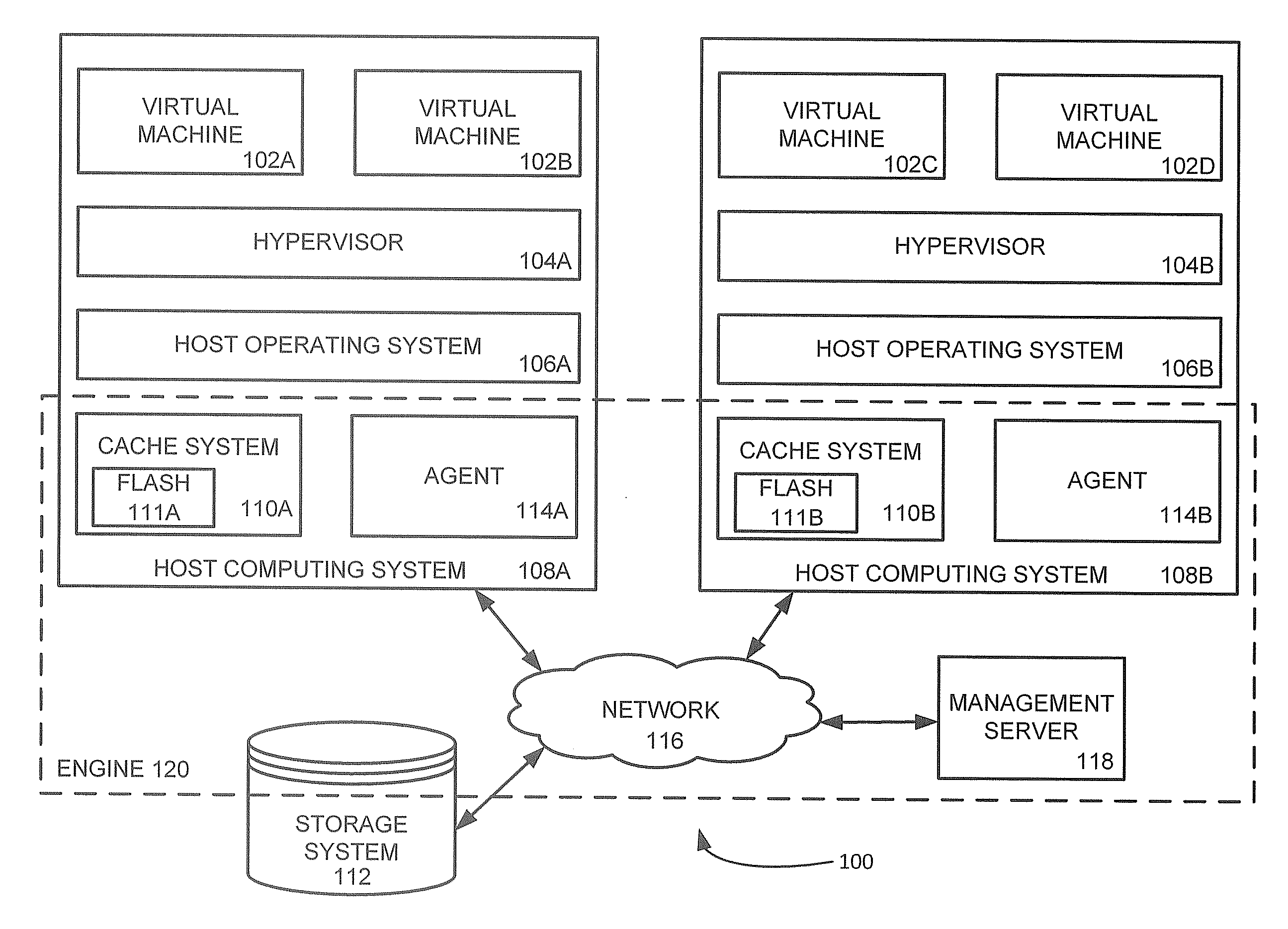
[0026]Replication of data is accomplished in the present approach according to defined fault domains which reflect, either physically or virtually, the topology of a networked computing environment. In particular, defined fault domains are sets of host computing systems that can reflect different physical locations, different server racks, or any other topology of the environment. The fault domains are then used to control where cached data is to be replicated when running in a write back mode. Further, although a defined fault domain can include any host computing system in the environment, in a preferred embodiment each defined fault domain will only include those host computing systems that share a common exposure to some fault, thereby avoiding a fault occurring in one defined fault domain from affecting another defined fault domain thus ensuring the advantages of data replication. Further, unlike known data replication approaches, the present approach replicates such data accor...


PUM


Abstract

Fault domains are defined which reflect, either physically or virtually, the topology of a networked computing environment. These defined fault domains are then used to control where cached data is replicated when running in a write back cache mode. Unlike known replication approaches, the present approach replicates such data according to a user's defined data policy and based on the defined fault domains thereby avoiding the user having to keep track of changes in computing system configurations or update their data policy when virtual machines migrate from one host computing system to another.

Description

BACKGROUND[0001]1. Field[0002]This non-provisional U.S. patent application relates generally to distributed cache data systems and more specifically to managing replication of such cached data in such systems.[0003]2. Description of Related Art[0004]In computing systems, a cache is a memory system or subsystem that transparently stores data so that future requests for that data can be served faster. As an example, many modern microprocessors incorporate an instruction cache holding a number of instructions; when the microprocessor executes a program loop where the same set of instructions are executed repeatedly, these instructions are fetched from the instruction cache, rather than from an external memory device at a performance penalty of an order of magnitude or more.[0005]In other environments, such as where a computing system hosts multiple virtual machines under the control of a hypervisor, with each virtual machine running one or more applications, caching of objects stored o...

Claims


Application Information

Patent Timeline
IPC IPC(8): G06F11/20G06F12/08
CPCG06F11/2069G06F12/0815G06F2212/608G06F2201/805G06F2212/1032G06F2201/885G06F12/0804G06F12/0868G06F2212/152G06F2212/222G06F2212/284G06F2212/311G06F2201/815G06F11/2094G06F11/2097G06F11/3055G06F11/14
Inventor JOSHI, AKHILESH MANOHARMULEY, DEEPAK DILIPCROWE, BRYANVAGHANI, SATYAM B.NATARAJAN, SHANKAR VILAYANNUR
Owner PERNIXDATA
Learn More