
Solar Panel with Pivoting Side Supports

a solar panel and side support technology, applied in the direction of solar heat collector mounting/support, solar heat collector safety, lighting and heating apparatus, etc., can solve the problems of increasing the overall system cost, the initial cost of the system should not be significantly increased, and the cost of solar panels and other such components. to achieve the effect of reducing the cost and labor

Active Publication Date: 2016-10-27
PATTON ENG
View PDF2 Cites 10 Cited by
  • Summary
  • Abstract
  • Description
  • Claims
  • Application Information

AI Technical Summary

Benefits of technology

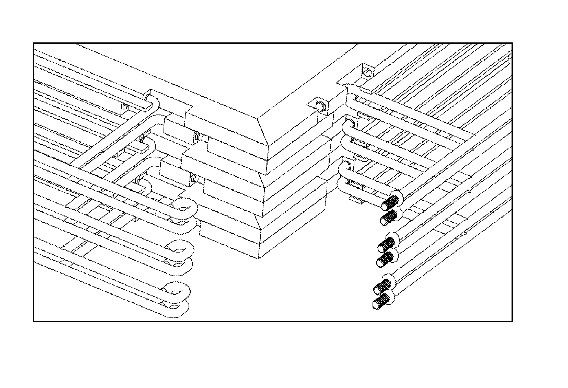
The patent describes a system where panels can be attached to both edges and surface mounts using adjustable supports. These supports can also be folded, and when not in use, stack in a compact way to save money and labor during packaging and shipping. The technical effect is a more versatile and efficient attachment system for panels.

Problems solved by technology

In addition, the initial cost of the system should not be increased significantly for simply the action of installing it on a pre-existing roof or other surface.
Furthermore, the cost of the solar panels and other such componentry itself is significant enough that the cost of an underlying structure, should not be so large as to greatly increase the cost of the overall system.
The more time an installer needs to spend on a roof or other area installing individual componentry, the more expensive the overall system is to a user.
This Laminate, 3, is also, more expensive and the Cell Area, 5, temperature is hotter due to less head dissipation which reduces the output power efficiency of the Solar Panel, 10.

Method used


Image

  • Solar Panel with Pivoting Side Supports
  • Solar Panel with Pivoting Side Supports
  • Solar Panel with Pivoting Side Supports

Examples


Embodiment Construction

[0131]As mentioned earlier, the present invention includes a variety of aspects, which may be combined in different ways. The following descriptions are provided to list elements and describe some of the embodiments of the present invention. These elements are listed with initial embodiments, however it should be understood that they may be combined in any manner and in any number to create additional embodiments. The variously described examples and preferred embodiments should not be construed to limit the present invention to only the explicitly described systems, techniques, and applications. Further, this description should be understood to support and encompass descriptions and claims of all the various embodiments, systems, techniques, methods, devices, and applications with any number of the disclosed elements, with each element alone, and also with any and all various permutations and combinations of all elements in this or any subsequent application.

[0132]FIGS. 11 to 117 s...


PUM


Abstract

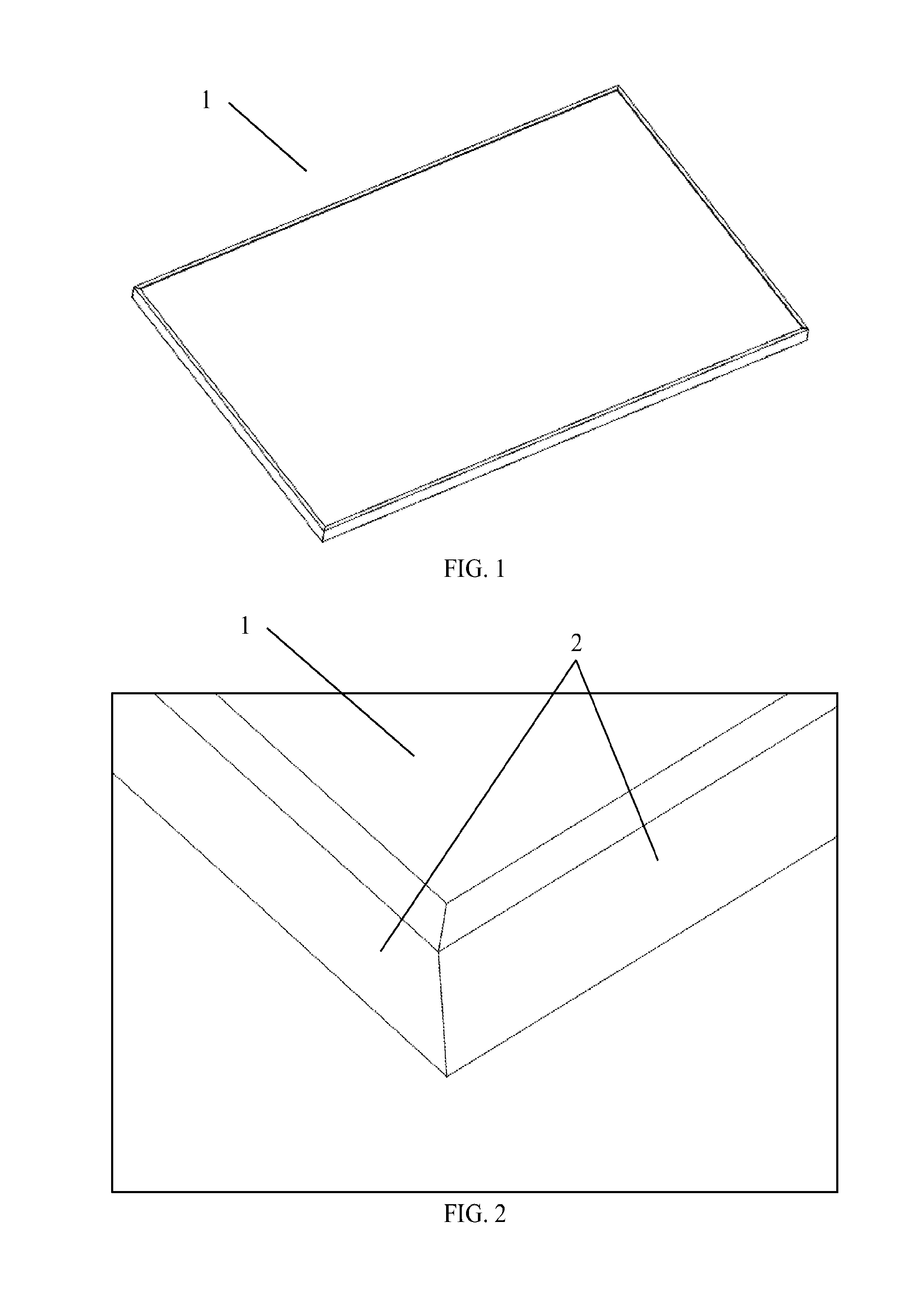
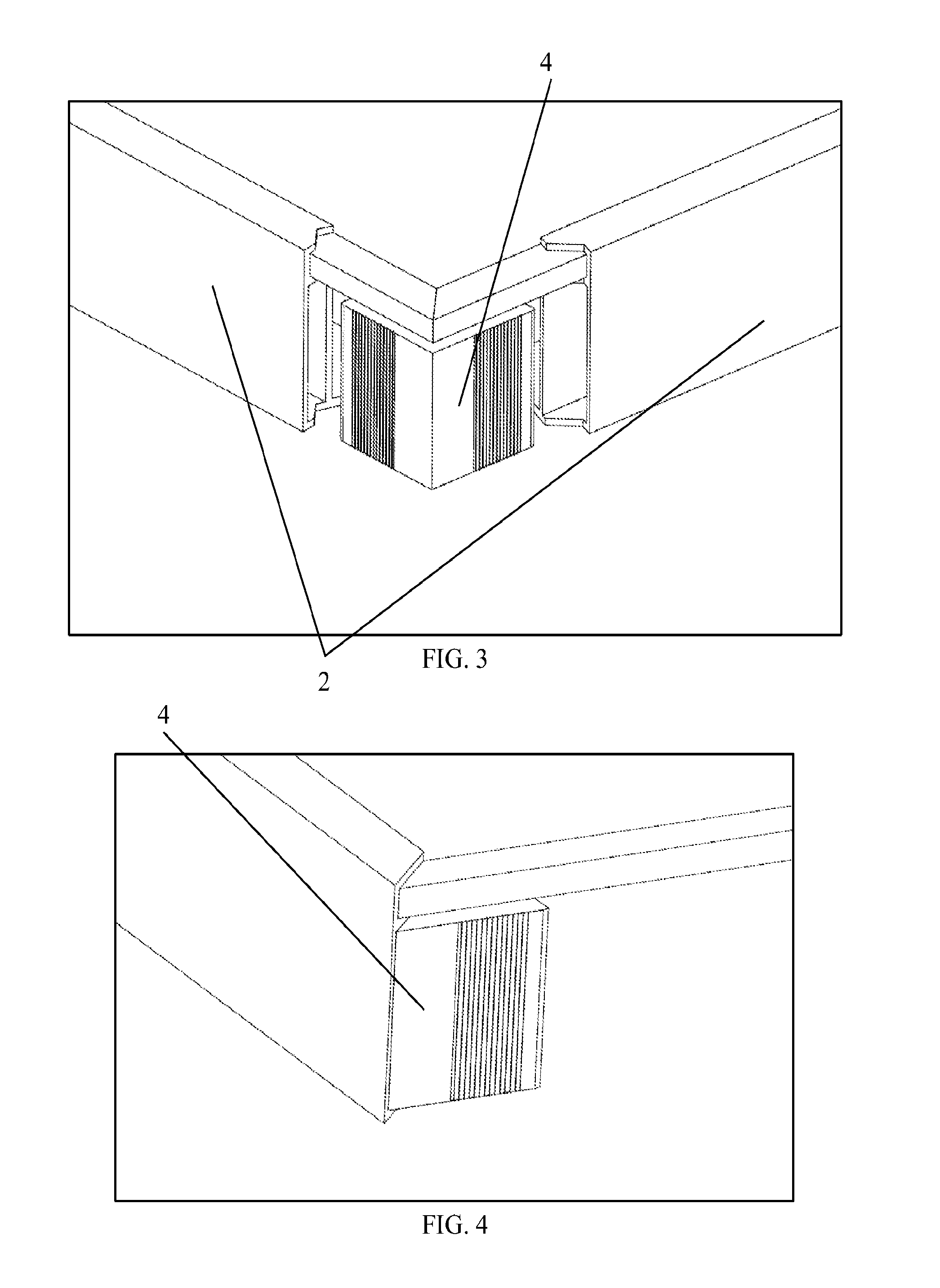
A folded down support (12) allows for stronger solar panels (10) and the support replaces most of the solar racking required for solar installation which further reduces the cost of the photovoltaic solar system. The solar panels (10) can be arranged so that solar panels form a solar collector solar panel array. The solar panel (10) can be set on a surface by itself or with ballast (43). It can also be attached to the surface by fastening the solar panel to the side supports. If the solar panel frame and supports are electrically conductive, the design allows for self electrical grounding between these conductive parts when the side supports are pivoted to the down position. The folded up support allows for high density storage and shipping.

Description

TECHNICAL FIELD[0001]The inventive technology disclosed herein has application in the field of packaging, shipping, and mounting solar panels.BACKGROUND[0002]The field of solar power has become very important. Solar power systems can be installed in huge seas as well as for individual residential and commercial usage. These individual systems can supply power to an underlying structure, and can also supply excess power into the grid or the like. For individual systems, it is not uncommon to locate these systems on the roofs of buildings. These roofs can be angled roofs or flat roofs. In many commercial applications a flat roof is frequently encountered and the solar panel system is placed on the roof itself. In order to remain economic, it is not only important that individual solar panels or the like produce a significant amount of power, but it can also be important that both the materials and structures be reasonably priced, and that the actual installation be achieved without to...

Claims


Application Information

Patent Timeline
IPC IPC(8): H02S30/10H02S20/24H02S20/23H01L31/042
CPCH02S30/10H02S20/23H02S20/24H01L31/042H01L31/02Y02E10/50Y02E10/47F24S40/85F24S2025/012F24S25/65F24S2025/02F24S25/61F24S25/20Y02B10/10F24S25/60F24S25/63F24S2025/01F24S25/10F24S25/12
Inventor PATTON, JOHN C.
Owner PATTON ENG
Learn More