Supercharge Your Innovation With Domain-Expert AI Agents!

Imaging apparatus, and imaging system

a technology which is applied in the field of imaging apparatus and imaging system, can solve the problems of deteriorating convenience, user's inability to fully recognize the functions assigned to the operation unit, and the difficulty of instantaneously operating the imaging apparatus as intended by the user, so as to achieve the effect of not deteriorating convenien

Active Publication Date: 2016-10-27
OM DIGITAL SOLUTIONS CORP
View PDF2 Cites 4 Cited by
  • Summary
  • Abstract
  • Description
  • Claims
  • Application Information

AI Technical Summary

Benefits of technology

The patent is about a camera system that is easier to use. This makes it convenient for people to take pictures.

Problems solved by technology

Such an imaging apparatus allows the functions to be allocated to the operation units suitably to individual preference, but the problem is that the user needs to recognize the function allocated to a certain operation unit.
For example, when there is a function that is not frequently used, when the allocation of the favorite function has been changed, or when the functions allocated to the operation units have been changed, there is a possibility that the user does not fully recognize the functions allocated to the operation units.
In this case, the problem is that instantaneously operating the imaging apparatus as intended by the user is more difficult, which may lead to deterioration of convenience.

Method used


Image

  • Imaging apparatus, and imaging system
  • Imaging apparatus, and imaging system
  • Imaging apparatus, and imaging system

Examples


first embodiment

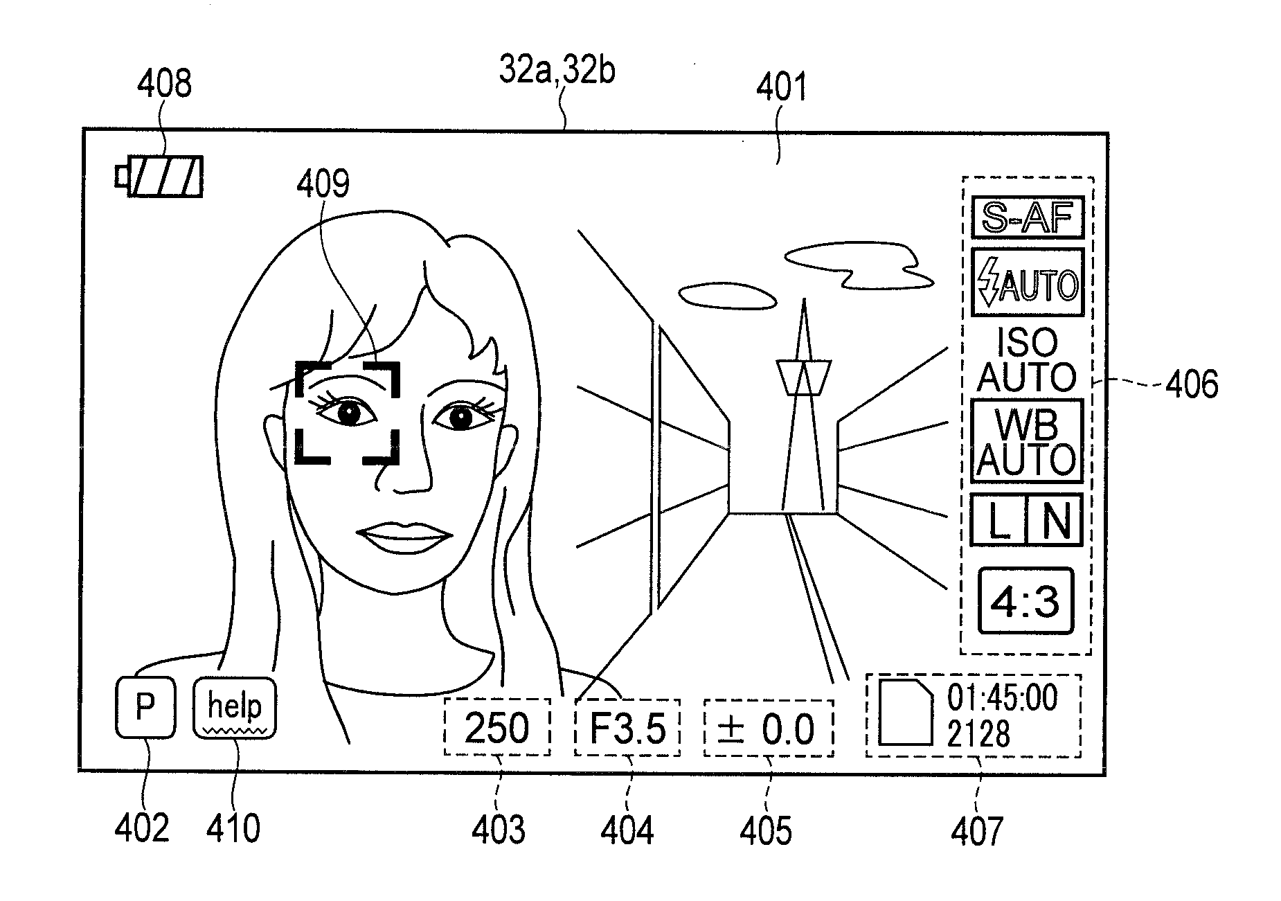
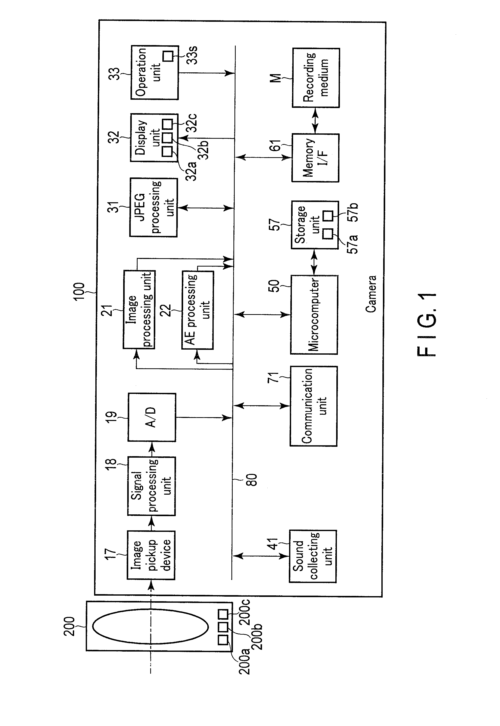
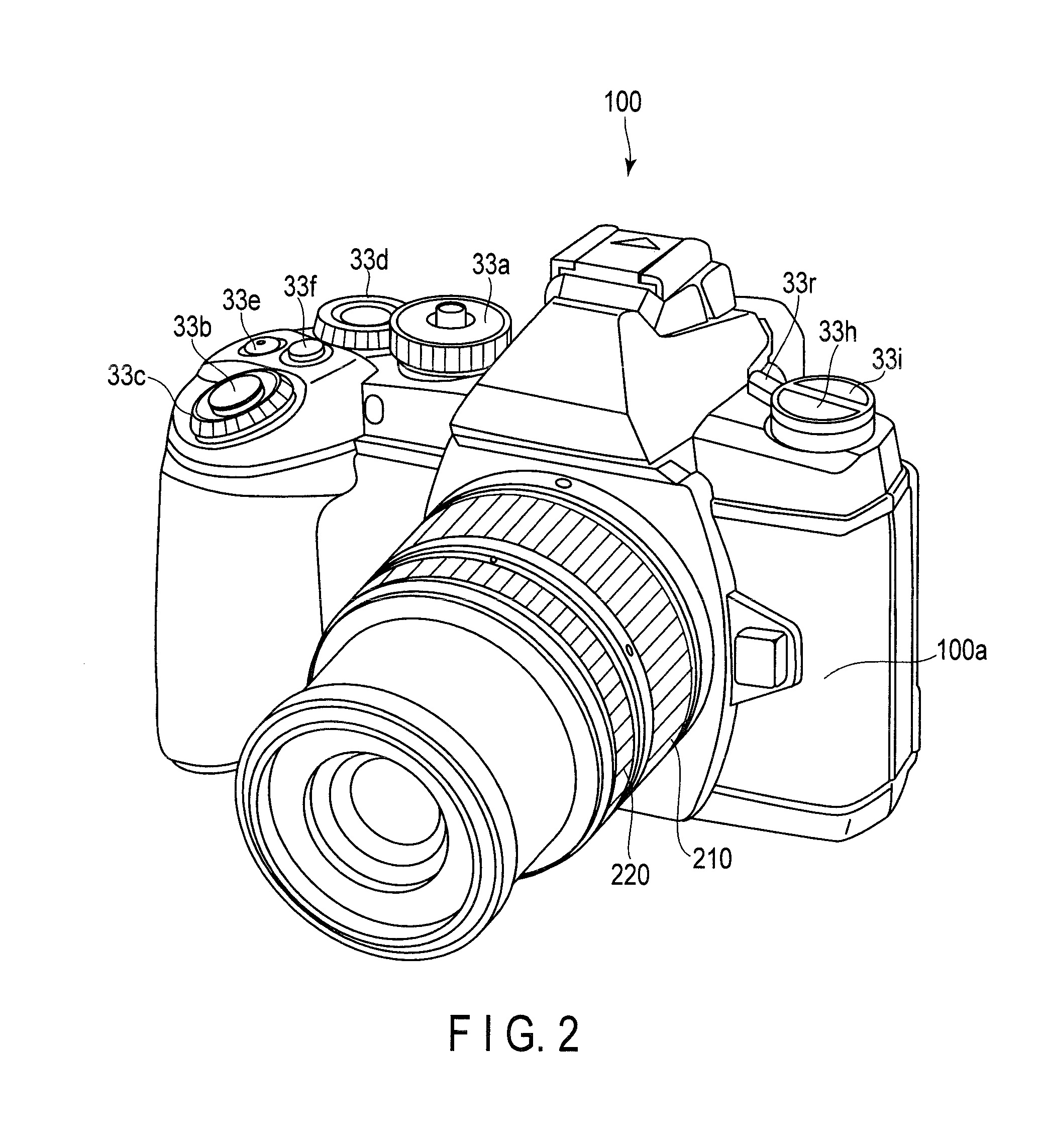
[0031]FIG. 1 shows an example of a control system of an imaging apparatus 100, and an imaging system 1 including the imaging apparatus 100. FIG. 2 and FIG. 3 show an example of the exterior of the imaging apparatus 100.

[0032]The imaging apparatus 1 includes the imaging apparatus 100 and an interchangeable lens (hereinafter referred to as a lens 200). The imaging system 1 may further include, for example, a tablet PC, a smartphone, or a slate PC (portable terminal) 300 such as a PC in which an input device such as a keyboard is combined with a slate-shaped display device.

[0033]The imaging apparatus 100 and the slate PC 300 can communicate with each other in a wired or wireless manner. The imaging apparatus 100 can, for example, perform an imaging operation and change various parameters under the control of the slate PC 300. Moreover, the slate PC 300 can reproduce images or moving images stored in a recording medium in the imaging apparatus 100.

[0034]The imaging apparatus 100 acquire...

second embodiment

[0190]FIG. 15 to FIG. 17 show an example of a lens-type imaging apparatus 500 which operates in cooperation with the slate PC 300. FIG. 15 shows an example of a control system of the imaging apparatus 500. FIG. 16 and FIG. 17 show an example of the exterior of the imaging apparatus 500.

[0191]The lens-type imaging apparatus 500 can receive various control signals from the slate PC 300, for example, a tablet PC, a smartphone, or a PC in which an input device such as a keyboard is combined with a slate-shaped display device, perform imaging processing on the basis of the received control signals, and save images or moving images in the recording medium M. Further, the lens-type imaging apparatus 500 can send the images or moving images saved in the recording medium M to the slate PC and then display the images or moving images. Moreover, the lens-type imaging apparatus 500 can acquire through-images, send the through-images to the slate PC 300, and display the through-images.

[0192]The ...


PUM


Abstract

According to the present invention, an imaging apparatus includes: a screen generating unit which generates a help screen by displaying allocation parameter corresponding to each of operation units on an operation unit layout drawing indicating positions of the operation units on the basis of a parameter database showing the operation unit allocated to each of the allocation parameters; and a display change judgment unit which judges whether to change the display state of the operation unit layout drawing, wherein the screen generating unit changes the angle of the operation unit layout drawing when there are operation unit layout drawings drawn from different angles and when the display change judgment unit judges to change the display state.

Description

CROSS-REFERENCE TO RELATED APPLICATIONS[0001]This application is a Continuation Application of PCT Application No. PCT / JP2015 / 059216, filed Mar. 25, 2015 and based upon and claiming the benefit of priority from Japanese Patent Application No. 2014-183961, filed Sep. 10, 2014, the entire contents of all of which are incorporated herein by reference.BACKGROUND OF THE INVENTION[0002]1. Field of the Invention[0003]The present invention relates to an imaging apparatus, and an imaging system.[0004]2. Description of the Related Art[0005]An imaging apparatus generally comprises an image pickup device which acquires an image on the basis of light, an optical system such as a lens which forms the light into an image on the image pickup device, and, for example, a liquid crystal or organic EL display device. The imaging apparatus comprises operation units to which functions for changing set values of parameters regarding imaging such as an aperture value (F value), a shutter speed (SS), ISO se...

Claims


Application Information

Patent Timeline
Patent Type & Authority Applications(United States)
IPC IPC(8): H04N5/232G03B17/18
CPCH04N5/23222H04N5/23293G03B17/18H04N5/23203H04N5/23216H04N23/66H04N23/62H04N23/667H04N23/632H04N23/635H04N23/64
Inventor ARAI, HIROZUMI
Owner OM DIGITAL SOLUTIONS CORP
Features
  • R&D
  • Intellectual Property
  • Life Sciences
  • Materials
  • Tech Scout
  • Unparalleled Data Quality
  • Higher Quality Content
  • 60% Fewer Hallucinations
Learn More