Method and apparatus for investigating a sample by means of optical projection tomography

a tomography and optical projection technology, applied in the field of tomographic investigation of samples, can solve the problems of high cost, inflexible use of microscopes, and complex construction of microscopes, and achieve the effect of good stability, modification of illumination location and/or alignment of illuminating light bundles

Active Publication Date: 2016-11-03
LEICA MICROSYSTEMS CMS GMBH
View PDF23 Cites 6 Cited by
  • Summary
  • Abstract
  • Description
  • Claims
  • Application Information

AI Technical Summary

Benefits of technology

[0038]The illuminating light deflecting means and / or the transmitted light deflecting means can advantageously be arranged on the objective or on the further objective. This has the advantage that large additional stand parts, which project from outside into the sample region and would themselves take up space, are not required. In addition, a placement on the objective or on the further objective ensures good stability, since the objectives themselves must already be held in stable fashion.
[0039]In a particular embodiment the illuminating light deflecting means and / or the transmitted light deflecting means are arranged movably, in particular displaceably and / or tiltably, on the objective or on the further objective. This kind of embodiment has the very particular advantage that the illumination location and / or the alignment of the illuminating light bundle can be modified by movement of the illuminating light deflecting means into a different position or into a different orientation. Analogously, the position and / or orientation of the transmitted light bundle can be modified by a movement of the transmitted light deflecting means into a different position or into a different orientation.

Problems solved by technology

Disadvantageously, the microscope is of very complex construction; in particular, three objectives precisely aligned with one another are required simultaneously in order to focus illuminating light onto the sample and to receive detected light, emerging from the sample, for the respective detectors.
The microscope moreover is not flexibly usable.
For example, the sample must obligatorily be moved relative to the microscope so that three-dimensional images of the sample can be generated; this is cumbersome and not possible with every type of sample, since the experimentation space is restricted by the three objectives.
Implementation of such a microscope in a conventional microscope configuration, in particular using a conventional microscope stand, is moreover not possible or at best possible only with difficulty, making the manufacture of such a microscope complex and costly.

Method used


Image

  • Method and apparatus for investigating a sample by means of optical projection tomography
  • Method and apparatus for investigating a sample by means of optical projection tomography
  • Method and apparatus for investigating a sample by means of optical projection tomography

Examples


Embodiment Construction

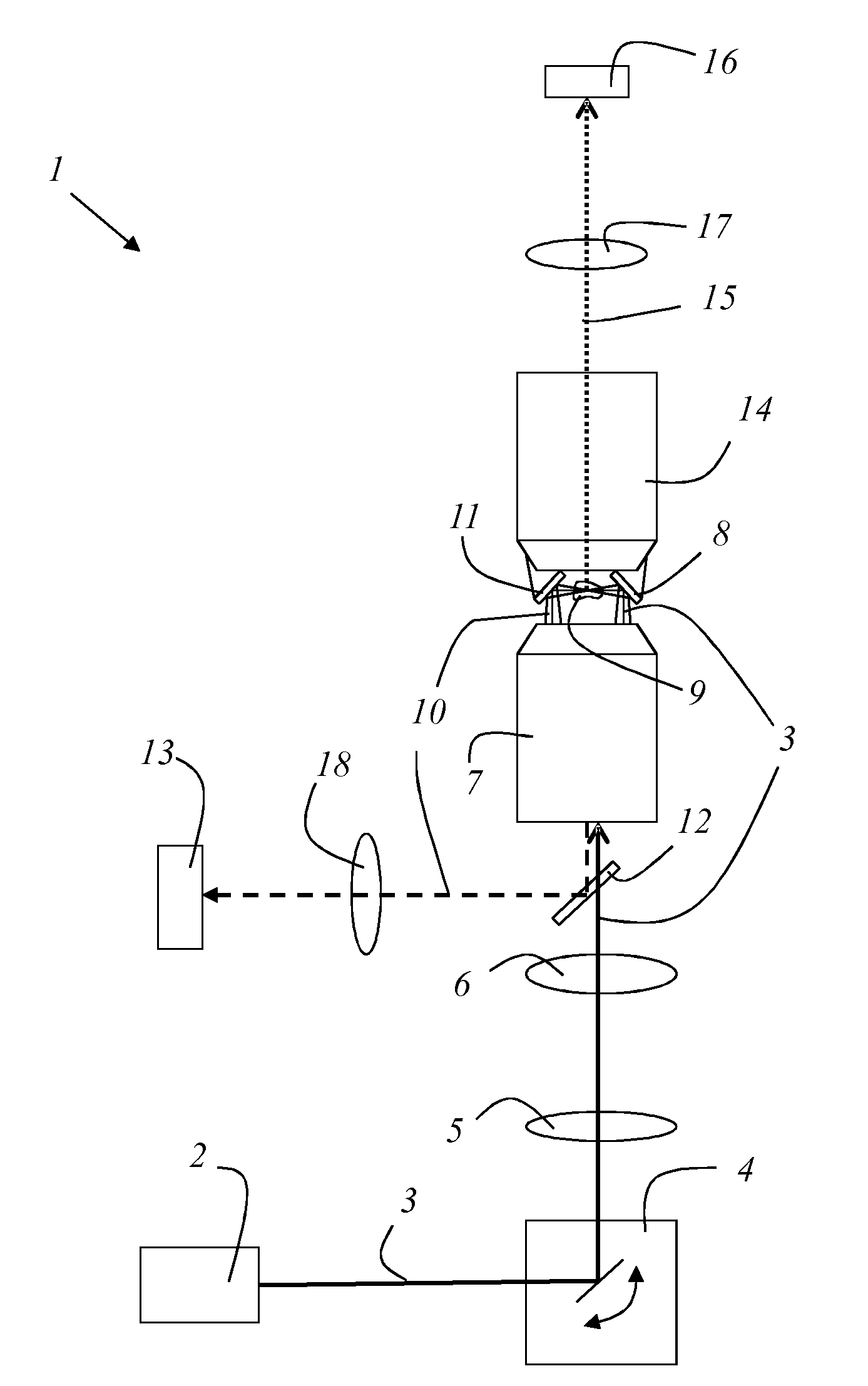
[0047]FIG. 1 shows an exemplifying embodiment of an apparatus 1 according to the present invention. The apparatus comprises a light source 2 that can be embodied in particular as a laser. Light source 2 emits an illuminating light bundle 3 that is deflected by a beam deflecting device 4 adjustable in terms of deflection angle. After deflection, illuminating light bundle 3 proceeds through a scanning lens 5 and a tube lens 6, passes through a beam splitter 12, and travels to an objective 7 that focuses illuminating light bundle 3.

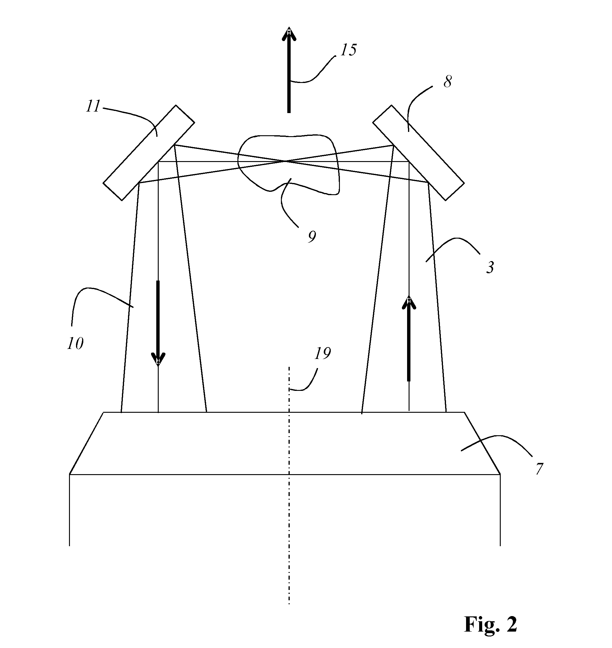
[0048]Beam deflecting device 4 is adjusted in such a way that illuminating light bundle 3 passes through the objective pupil of objective 7 at a tilt with respect to the optical axis so that it leaves objective 7 eccentrically, i.e. with a lateral offset with respect to the optical axis of objective 7, and then strikes an illuminating light deflecting means 8 that deflects illuminating light bundle 3, preferably through approximately 90 degrees, to a sample....


PUM

PropertyMeasurementUnit
angleaaaaaaaaaa
angleaaaaaaaaaa
deflection angleaaaaaaaaaa

Abstract

The invention relates to a method for tomographic investigation of a sample (9), in which method a sample (9) is illuminated with an illuminating light bundle (3) and in which a transmitted light bundle (10) that contains the light of the illuminating light bundle (3) transmitted through the sample (9) is detected with a transmission detector (13). The invention further relates to an apparatus for tomographic investigation of a sample (9). Provision is made that the illuminating light bundle (3) and the transmitted light bundle (10) pass in opposite propagation directions through the same objective (7).

Description

CROSS-REFERENCE TO RELATED APPLICATIONS[0001]The present application is the U.S. national phase of International Application No. PCT / EP2014 / 078335 filed Dec. 17, 2014, which claims priority of German Application No. 10 2013 226 277.9 filed Dec. 17, 2013, the entirety of which is incorporated herein by reference.FIELD OF THE INVENTION[0002]The invention relates to a method for tomographic investigation of a sample, in which method a sample is illuminated with an illuminating light bundle and in which a transmitted light bundle that contains the light of the illuminating light bundle transmitted through the sample is detected with a transmission detector.[0003]The invention furthermore relates to an apparatus for tomographic investigation of a sample, having a light source that generates an illuminating light bundle that illuminates the sample to be investigated, and having a transmission detector for detected a transmitted light bundle that contains light of the illuminating light bu...

Claims


Application Information

Patent Timeline
Patent Type & Authority Applications(United States)
IPC IPC(8): G01N21/59G01N21/64G02B21/00G01N21/47
CPCG01N21/59G01N21/47G01N21/6458G01N2201/10G01N2201/06113G01N2201/0636G01N2021/6491G02B21/0028G01N21/4795G02B21/088
Inventor KNEBEL, WERNERFOUQUET, WERNHERSIECKMANN, FRANK
Owner LEICA MICROSYSTEMS CMS GMBH
Why Eureka
Try Eureka