Liquid crystal display

a liquid crystal display and display technology, applied in non-linear optics, instruments, optics, etc., can solve problems such as easy failure of pixels, and achieve the effects of reducing or eliminating failures of pixels positioned near or at corners, preventing pixel failures, and minimizing the effect of external impa

Active Publication Date: 2016-11-03
SAMSUNG DISPLAY CO LTD
View PDF4 Cites 25 Cited by
  • Summary
  • Abstract
  • Description
  • Claims
  • Application Information

AI Technical Summary

Benefits of technology

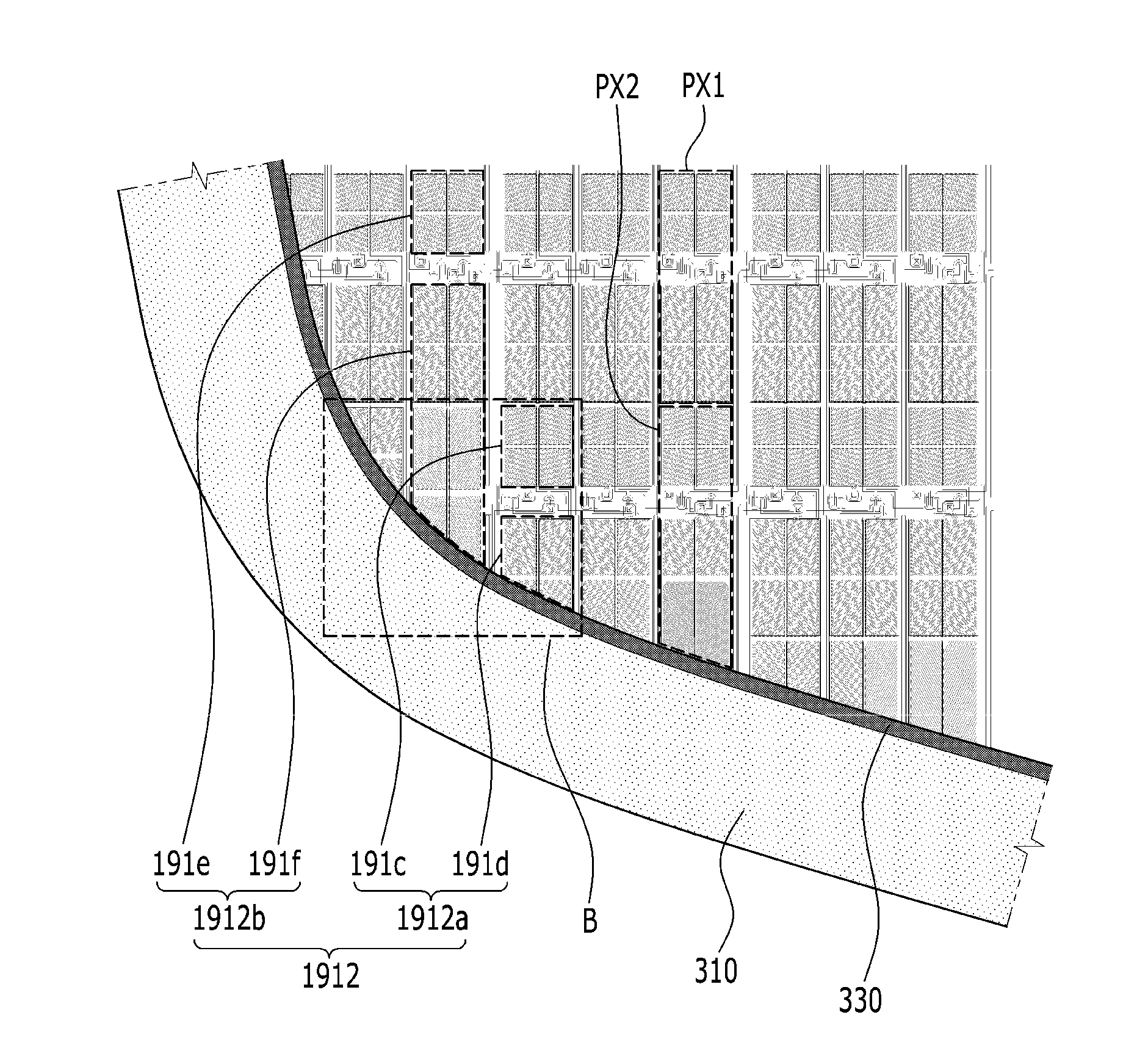
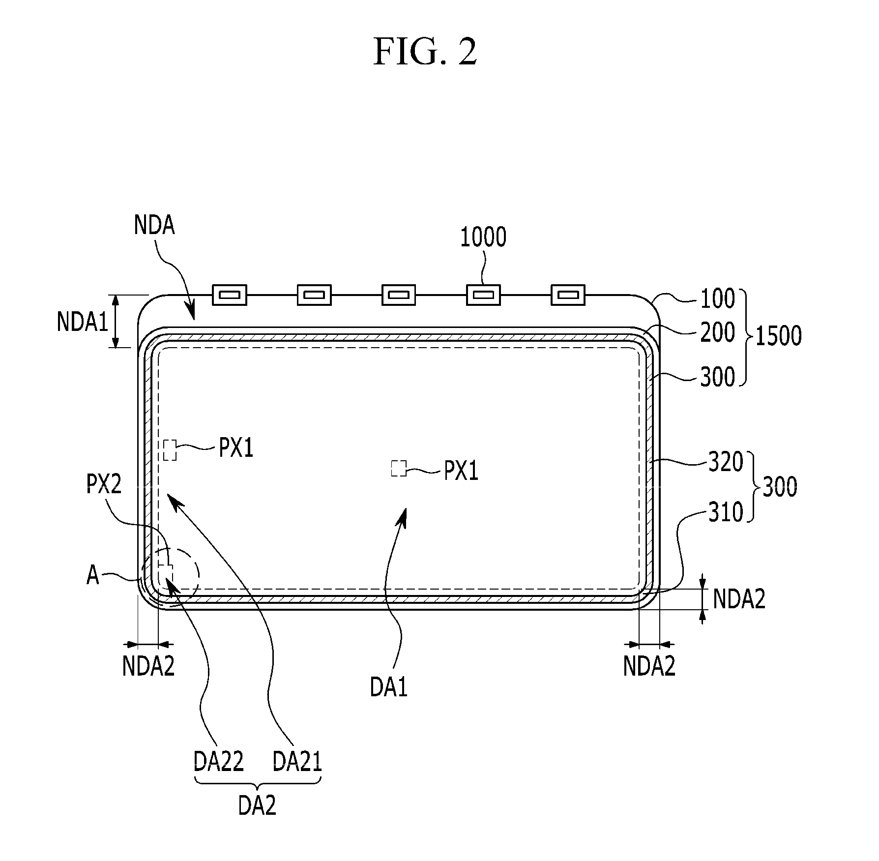
[0020]According to the present disclosure, by reducing or expanding the size of a corner pixel electrode of a corner pixel, the corner pixel electrode does not overlap the sealant, thereby preventing pixel failure. Accordingly, even if a perpendicularly formed sealant coating device is not separately used, failures of the pixels positioned near or at the corners may be reduced or eliminated.
[0021]Also, the corner sealant may be formed to be rounded and the corner of the liquid crystal display may be formed to be rounded to minimize the effect of an external impact and enhance the design characteristics.
[0022]Also, the sealant and the corner pixel do not overlap, such that a degree of the spread of the sealant is uniform in the assembly after a coating process. Accordingly, the non-uniform spread of the sealant that may occur when the sealant and the corner pixel overlap each other can be prevented.
[0023]In addition, by forming the dam made of the lower dam and the upper dam at positions facing each other inside the sealant, the sealant may be prevented from spreading to the display area when the lower panel and the upper panel are combined.

Problems solved by technology

When coating a sealant of the narrow bezel, it is difficult to perpendicularly form the sealant in four corners due to a limitation of a sealant coating device, and thus the sealant is formed of a curved line in the corners.
Accordingly, the pixels positioned close to the corners overlap the sealant such that pixel failure may easily occur.

Method used


Image

  • Liquid crystal display
  • Liquid crystal display
  • Liquid crystal display

Examples


Embodiment Construction

[0032]The present disclosure will be described more fully hereinafter with reference to the accompanying drawings, in which exemplary embodiments of the present disclosure are shown. As those skilled in the art would realize, the described embodiments may be modified in various different ways, without departing from the spirit or scope of the present disclosure.

[0033]In order to clearly describe the present disclosure, parts unrelated to the descriptions may be omitted. Throughout the present disclosure, like reference numerals refer to like or similar constituent elements.

[0034]In addition, the size and thickness of each configuration shown in the drawings are arbitrarily shown to facilitate understanding and ease of description, but the present disclosure is not necessarily limited thereto. In the drawings, the thickness of layers, films, panels, regions, etc., may be exaggerated for clarity. In the drawings, for better understanding and ease of description, the thicknesses of som...


PUM

PropertyMeasurementUnit
DAaaaaaaaaaa
widthaaaaaaaaaa
voltageaaaaaaaaaa

Abstract

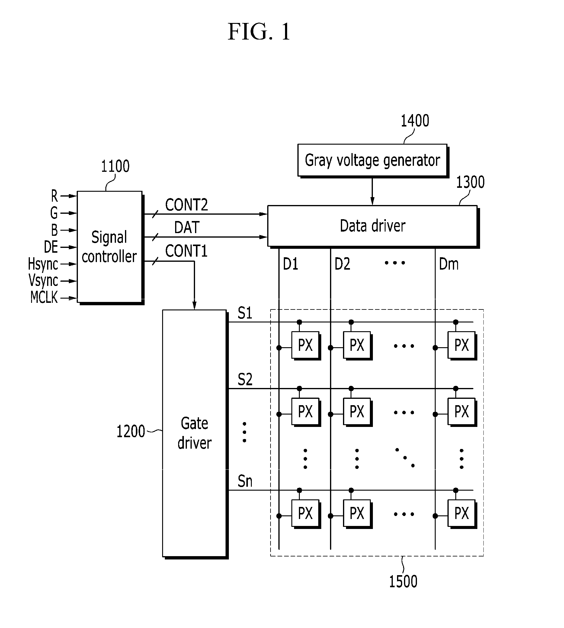
A liquid crystal display according to an exemplary embodiment includes a display substrate including a display area for displaying an image and a non-display area enclosing the display area; a plurality of normal pixels formed in an edge region among a center region of the display area and a peripheral area of the display area, and a plurality of corner pixels formed in a corner region of the peripheral area of the display area; and a sealant formed in the non-display area. A corner pixel of the plurality of corner pixels and the sealant are separated from each other.

Description

CROSS-REFERENCE TO RELATED APPLICATION[0001]This application claims priority to and the benefit of Korean Patent Application No. 10-2015-0062066 filed in the Korean Intellectual Property Office on Apr. 30, 2015, the disclosure of which is incorporated herein by reference in its entirety.BACKGROUND[0002]1. Field[0003]The present disclosure relates to a liquid crystal display.[0004]2. Description of the Related Art[0005]A liquid crystal display includes two sheets of display panels in which electrodes are formed, and a liquid crystal layer interposed between the two sheets of display panels. The liquid crystal display displays an image by generating an electric field on the liquid crystal layer by applying a voltage to the field generating electrodes, determining alignment directions of liquid crystal molecules of the liquid crystal layer by the generated electric field, and controlling the polarization of incident light.[0006]Recently, narrow bezel display devices have been developed...

Claims


Application Information

Patent Timeline
Patent Type & Authority Applications(United States)
IPC IPC(8): G02F1/1339G02F1/1368G02F1/1335G02F1/1343
CPCG02F1/1339G02F1/134309G02F2001/133388G02F1/133514G02F1/1368G02F1/134336G02F1/133388G02F1/134345
Inventor LEE, SANG-MYOUNGYU, SEUNG JUNSEO, O SUNGCHONG, JOONG GUN
Owner SAMSUNG DISPLAY CO LTD
Why Eureka
Try Eureka