
DC circuit breaker and method of use

a circuit breaker and direct current technology, applied in the direction of electronic switching, emergency protection arrangements for limiting excess voltage/current, pulse technique, etc., can solve the problems of electrical safety standards that cannot be met by solid state switches alone, solid state switches do not provide galvanic isolation provided by mechanical contactors, and current can leak through open solid state switches

Active Publication Date: 2016-11-03
GENERAL ELECTRIC CO
View PDF6 Cites 38 Cited by
  • Summary
  • Abstract
  • Description
  • Claims
  • Application Information

AI Technical Summary

Benefits of technology

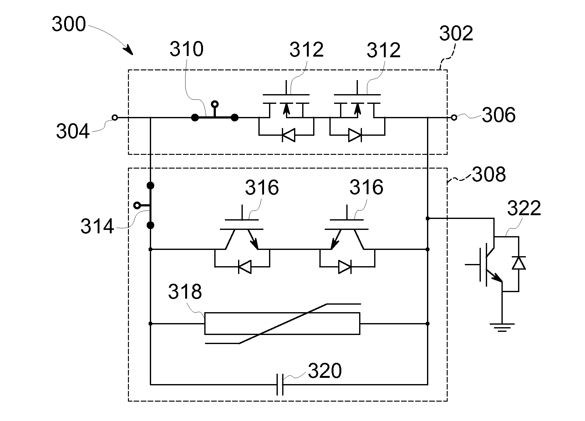
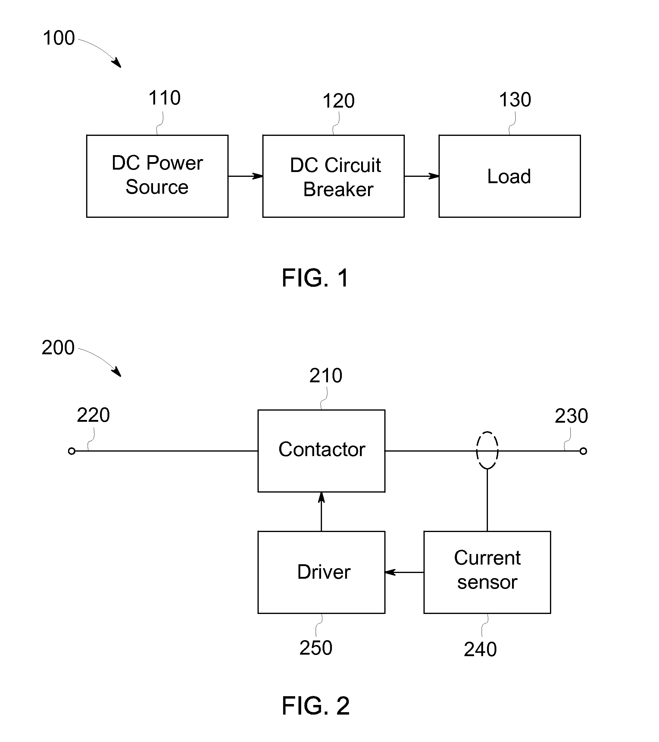
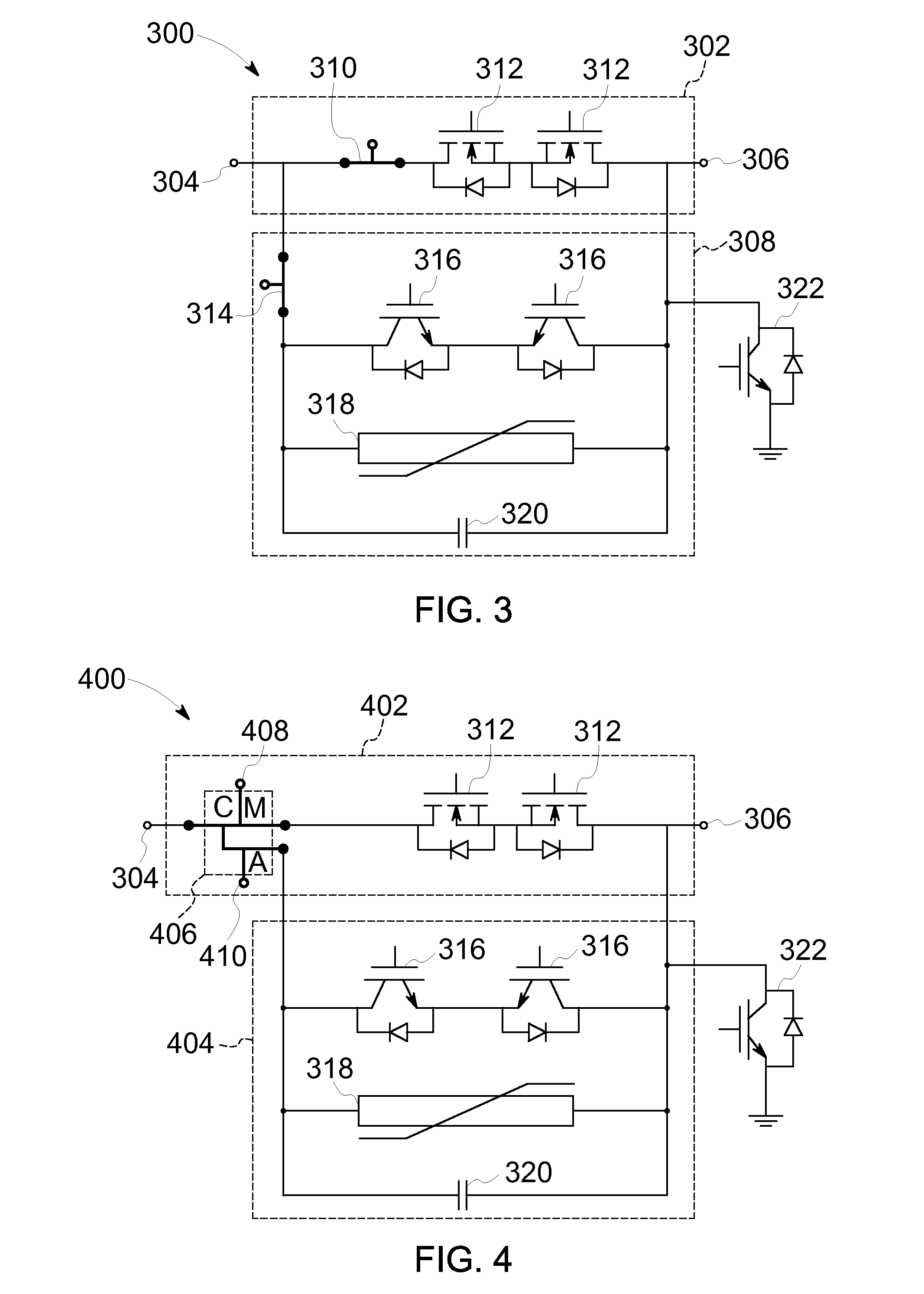
The patent describes a direct current circuit breaker that has a main circuit and a transient circuit. The main circuit has a main contactor and a first solid state switch, while the transient circuit has a second solid state switch and an auxiliary contactor. When there is a main-path current through the first solid state switch, the second solid state switch is closed to divert the current to the transient circuit. When the main-path current is too high, the first solid state switch opens and the main contactor opens. When the main-path current is too low, the second solid state switch opens. The transient circuit is designed to handle high transient-path current and the auxiliary contactor opens when the current is too low. This design allows for safer and more efficient use of direct current circuit breakers in power distribution systems.

Problems solved by technology

Known circuit breakers also utilize solid state switches, although solid state switches do not provide the galvanic isolation provided by mechanical contactors.
Consequently, current can leak through an open solid state switch.
For this reason, among others, solid state switches alone often do not satisfy some electrical safety standards.
Arcs are high-energy and can be damaging to components, especially to breaker contact surfaces.
Arcs can be dangerous for people near the arc, and also to those relying on the disconnection of the circuit, because the arc delays the break of the circuit.
Arcs can also create electromagnetic interference issues that present further safety concerns.
In contrast, DC circuit breakers must interrupt a non-zero current, which makes arcs significantly more likely and requires greater speed and force.
The likelihood of arcs in DC circuit breakers drives their costs up and generally reduces their service life.

Method used


Image

  • DC circuit breaker and method of use
  • DC circuit breaker and method of use
  • DC circuit breaker and method of use

Examples


Embodiment Construction

[0016]In the following specification and the claims, a number of terms are referenced that have the following meanings.

[0017]The singular forms “a”, “an”, and “the” include plural references unless the context clearly dictates otherwise.

[0018]“Optional” or “optionally” means that the subsequently described event or circumstance may or may not occur, and that the description includes instances where the event occurs and instances where it does not.

[0019]Approximating language, as used herein throughout the specification and claims, may be applied to modify any quantitative representation that could permissibly vary without resulting in a change in the basic function to which it is related. Accordingly, a value modified by a term or terms, such as “about”, “approximately”, and “substantially”, are not to be limited to the precise value specified. In at least some instances, the approximating language may correspond to the precision of an instrument for measuring the value. Here and th...


PUM


Abstract

A direct current circuit breaker includes main circuit for carrying a main-path current, and a transient circuit for carrying a transient-path current. The main circuit includes a first solid state switch and a main contactor. The first solid state switch is coupled in series with the main contactor. The transient circuit is coupled in parallel with the main circuit. The transient circuit includes an auxiliary contactor coupled in series with a second solid state switch. The second solid state switch closes when the main-path current exceeds a first threshold. The first solid state switch then opens. The main contactor opens when the main-path current falls below a second threshold. Then the second solid state switch opens. The auxiliary contactor opens when the transient-path current falls below the second threshold and after the second solid state switch opens.

Description

BACKGROUND[0001]The field of the disclosure relates generally to direct current (DC) circuit protection systems and, more particularly, to a DC circuit breaker and a method of use thereof.[0002]Many known power circuits utilize circuit breakers to detect over-currents and break the circuit in response. Known circuit breakers utilize a mechanical contactor to make and break the circuit between a line side and a load side. When broken by a mechanical contactor, the circuit breaker provides galvanic isolation between the line side and the load side by a physical separation of the conductive path. The physical separation is between contacts of the mechanical contactor and occurs within a medium, such as air, for example, or another dielectric material. Known circuit breakers also utilize solid state switches, although solid state switches do not provide the galvanic isolation provided by mechanical contactors. Consequently, current can leak through an open solid state switch. For this r...

Claims


Application Information

Patent Timeline
IPC IPC(8): H02H9/02
CPCH02H9/02H02H3/087H02H7/222H03K17/165H03K17/6874H01H9/542H01H33/596
Inventor WANG, RUXIPRABHAKARAN, SATISH
Owner GENERAL ELECTRIC CO
Learn More