
Camera Mode Control

a camera mode and automatic technology, applied in the field of cameras, can solve the problems of inability to manually switch either of the cameras to the desired mode, and conventional camera systems fail to provide any mechanism for automatically determining

Active Publication Date: 2016-11-03
GOPRO
View PDF4 Cites 26 Cited by
  • Summary
  • Abstract
  • Description
  • Claims
  • Application Information

AI Technical Summary

Benefits of technology

This patent describes a camera system that can automatically switch between different modes to capture users' experiences. The system uses data from sensors and captured images to determine which mode to switch to, and can switch to a preferred mode based on the likelihood of an event occurring. This allows the camera to capture the best moments without requiring manual adjustments by the user. The technical effect of this patent is to provide a more efficient and effective way to automatically control the operation of a camera to capture the user's experience.

Problems solved by technology

The user would like to capture this jump with the ski-mounted camera taking a burst of multiple images and the helmet-mounted camera taking a high frame rate capture (for slow motion effect), but the user is unable to manually switch either of the cameras to the desired modes in the middle of the ski run.
Thus, conventional camera systems fail to provide any mechanism for automatically determining and switching to an operation mode that best captures a user experience.

Method used


Image

  • Camera Mode Control
  • Camera Mode Control
  • Camera Mode Control

Examples


example camera

Configuration

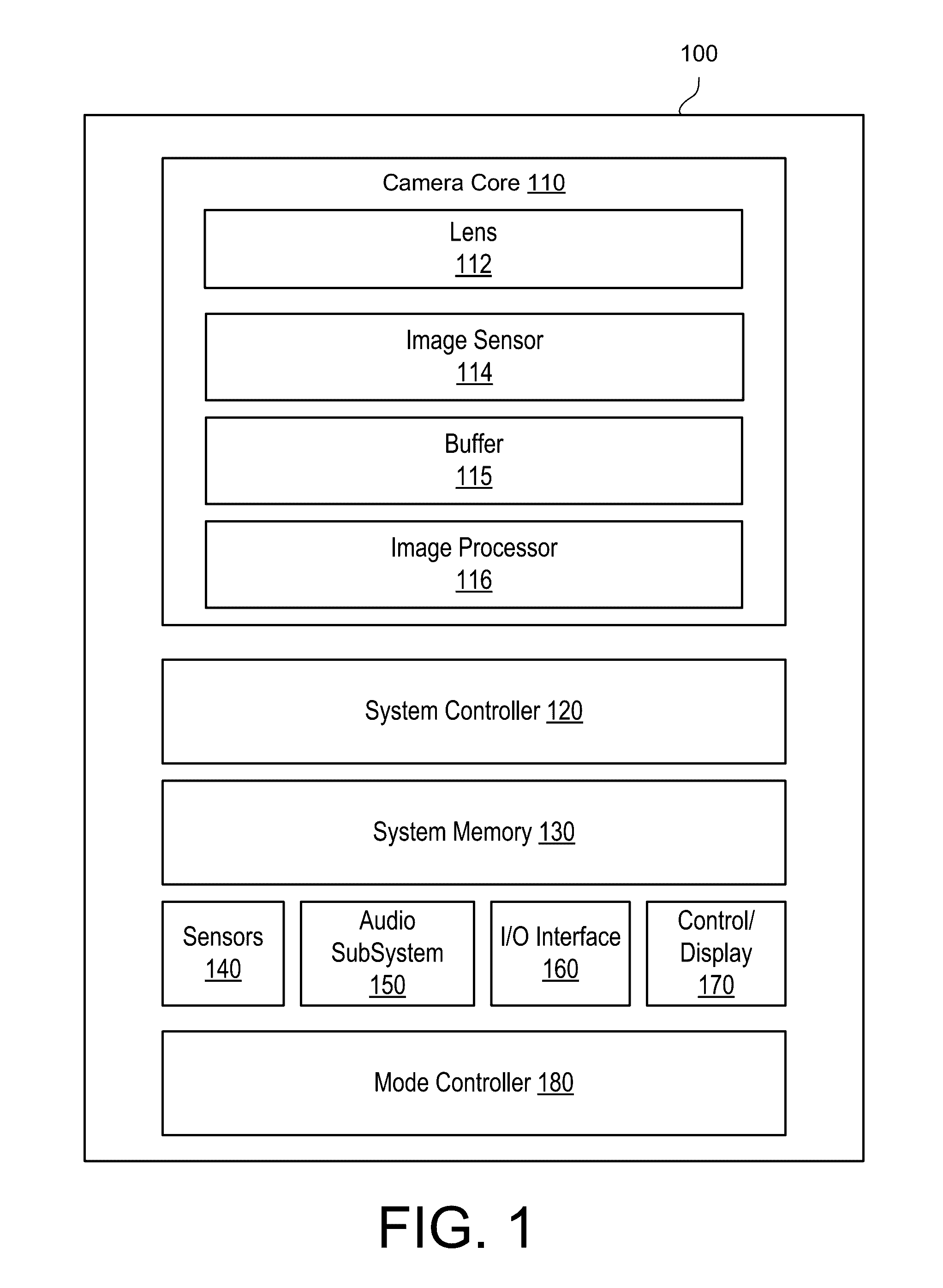
[0021]FIG. 1 is a block diagram illustrating a camera 100, according to one embodiment. In the illustrated embodiment, the camera 100 comprises a camera core 110 comprising a lens 112, an image sensor 114, and an image processor 116. The camera 100 additional includes a system controller 120 (e.g., a microcontroller or microprocessor) that controls the operation and functionality of the camera 130 and system memory 130 configured to store executable computer instructions that, when executed by the system controller 120 and / or the image processor 116, perform the camera functionalities described herein. In some embodiments, a camera 130 may include multiple camera cores 110 to capture fields of view in different directions which may then be stitched together to form a cohesive image. For example, in an embodiment of a spherical camera system, the camera 130 may include two camera cores 110 each having a hemispherical or hyperhemispherical lens that each captures a hemisp...


PUM


Abstract

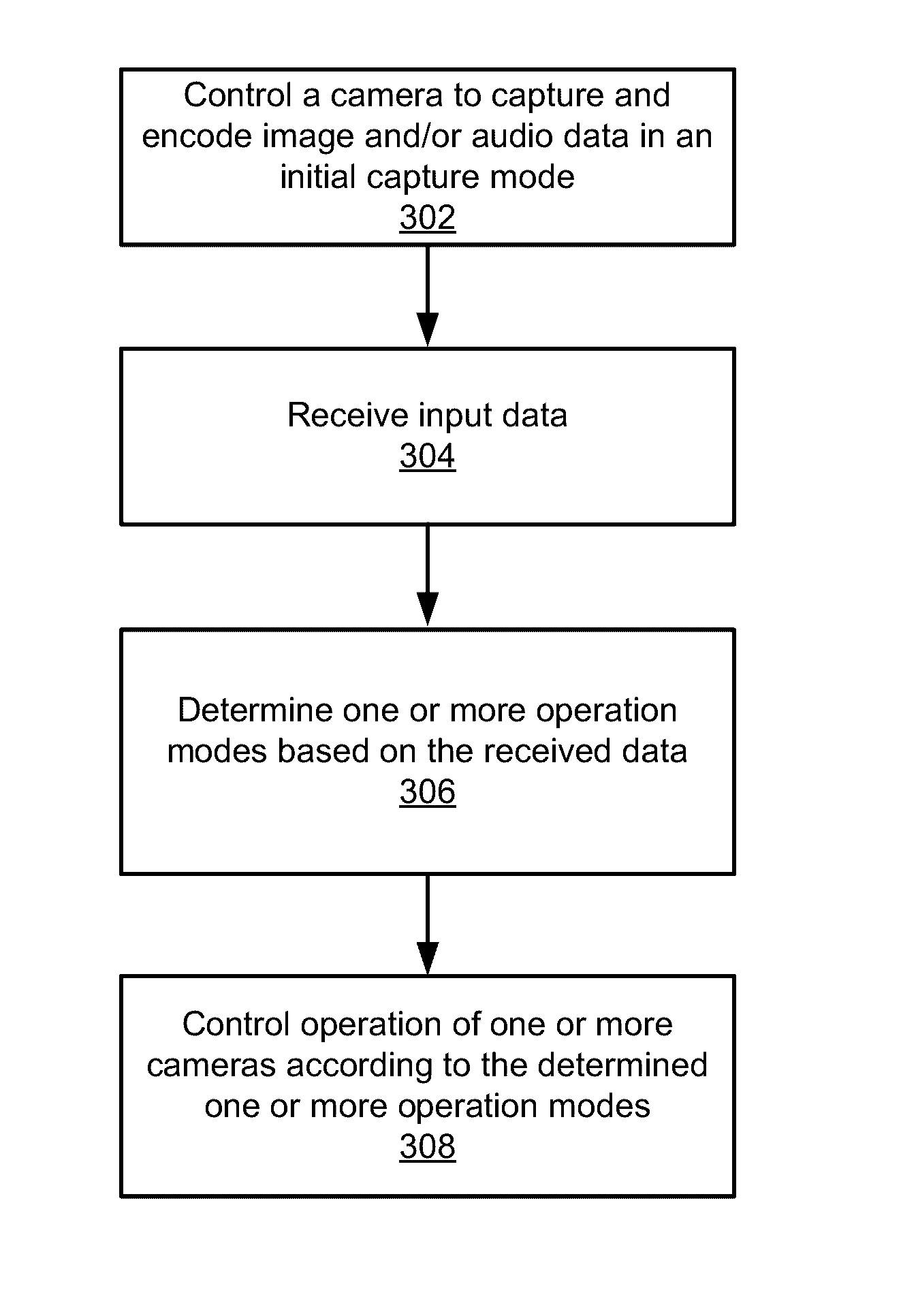
Cameras may monitor its operation and automatically switch between operation modes thereby to best capture users' experiences. Auxiliary sensor data collected by the one or more sensors and / or captured image data may be analyzed to determine when a camera should switch to a different operation mode. The auxiliary sensor data and / or the content of the captured images may include motion information indicating whether the camera or the captured scene has relatively high-motion, relatively low-motion, or no motion. Event(s) may be detected by analyzing the auxiliary sensor data and / or analyzing captured image data, and preferred operation mode(s) suitable for capturing the events can be determined. Each preferred operation mode may be associated with a confidence value. A camera may switch to a preferred operation mode for capturing an event if the event is determined with high confidence to take place at a time point.

Description

CROSS-REFERENCE TO RELATED APPLICATION(S)[0001]This application claims priority under 35 U.S.C. §119(e) to U.S. Provisional Patent Application Ser. No. 62 / 155,882, “Camera Mode Control,” filed May 1, 2015, which is incorporated herein by reference in its entirety.BACKGROUND[0002]1. Technical Field[0003]This disclosure relates to a camera, and more specifically, to automatically controlling an operation mode of a camera.[0004]2. Description of the Related Art[0005]Most capture devices allow for a variety of options and configurations for capturing image, video, and audio content. For example, a capture device can be configured to capture a single image, a time-lapsed burst of multiple images, or video captured at varying frames per second (e.g., 24 frames per second (fps), 30 fps, 120 fps, 240 fps, etc.) In a conventional capture device, a user manually selects a specific operation mode for capturing content. For action cameras used during activities such as skiing, snowboarding, sur...

Claims


Application Information

Patent Timeline
IPC IPC(8): H04N5/232H04N19/10H04N5/91
CPCH04N5/23245H04N19/10H04N5/91H04N5/23222H04N5/772H04N5/783H04N9/8211H04N23/60H04N23/661H04N23/651H04N23/667H04N23/6811H04N23/6812
Inventor AYALASOMAYAJULA, SHISHIR RAOBELAGUTTI SHIVANANDAPPA, RAVI KUMARCHINNAIYAN, ANANDHAKUMAR
Owner GOPRO
Learn More