Magnetic fence covering

a technology of magnets and fences, applied in the field of magnets, can solve the problems of needing replacement, affecting the appearance, and expensive fences, and achieve the effect of controlling the position of magnets

Inactive Publication Date: 2016-11-10
MICELI VANCE
View PDF4 Cites 2 Cited by
  • Summary
  • Abstract
  • Description
  • Claims
  • Application Information

AI Technical Summary

Benefits of technology

[0010]At least one magnet is fixedly attached to at least one of the top edge, the bottom edge, and the side edges. In the preferred embodiment, the at least one magnet is fixed to the planar sheet in proximity to the top edge. Preferably, the top edge is folded 180° towards the bottom edge and fixed to the planar sheet to define a magnet accommodating space. The top edge may be stitched to the planar sheet, heat sealed, glued, or otherwise adhered thereto. Further, the at least one magnet may be adhesively or otherwise attached to the planar sheet at a position in proximity to the top edge before the top edge is folded towards the bottom edge. Thus, the positioning of the magnets can be controlled.

Problems solved by technology

However, there are several drawbacks to this type of fence.
In particular, these fences are expensive, aesthetically displeasing, and prevent sunlight and airflow from entering the enclosed area.
However, the stich or glue will degrade over time and will need to be replace.
However, unitarily-formed tabs will increase the amount of wasted fabric during the manufacture process, thereby increasing the cost of the fence covering.
However, fence rails do not have a uniform thickness.
Thus, there will be undesirable variation in the height and placement of the fence covering.
Moreover, ensuring each snap is properly connected is a time-consuming process.
Third, to remove the fence covering, each zip tie must be cut thereby increasing the cost and the time necessary to install a fence covering.

Method used


Image

  • Magnetic fence covering
  • Magnetic fence covering

Examples


Embodiment Construction

[0015]Preferred embodiments of the present disclosure will be described hereinbelow with reference to the accompanying drawings. In the following description, well-known functions or constructions are not described in detail to avoid obscuring the present disclosure in unnecessary detail.

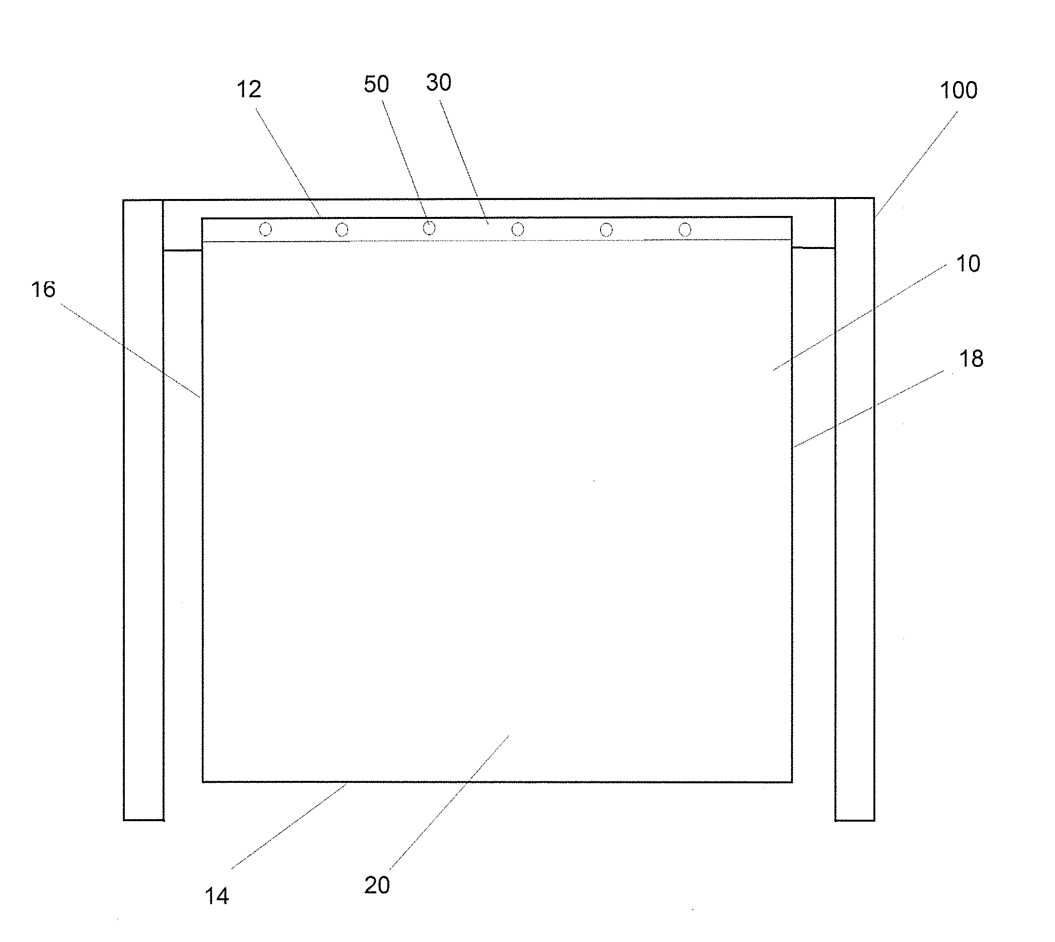
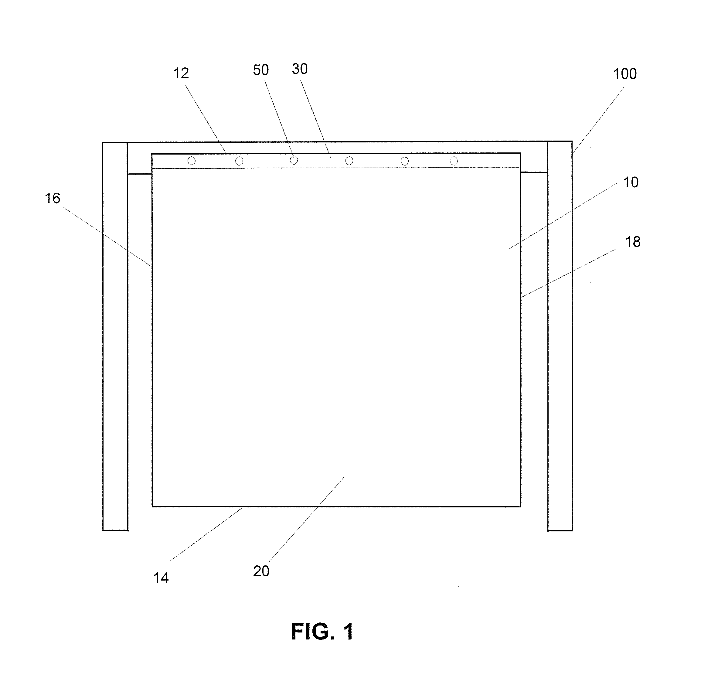
[0016]A magnetic fence covering 10 is provided for attachment to a fence 100. The fence covering 10 comprises a substantially planar sheet. The fence covering 10 may be plastic, fabric, or any other known and suitable material. The fence covering 10 is preferably flexible, but may have a degree of rigidity. The fence covering 10 has spaced apart top and bottom edges 12, 14 and side edges 16, 18 extending therebetween. The fence covering 10 is further defined by opposite front and rear surfaces 20, 22.

[0017]At least one magnet 50 is fixedly attached to at least one of the top edge 12, the bottom edge 14, and the side edges 16, 18. In the preferred embodiment, the at least one magnet 50 is fixed to th...


PUM

PropertyMeasurementUnit
magneticaaaaaaaaaa
areaaaaaaaaaaa
thicknessaaaaaaaaaa

Abstract

A magnetic fence covering is provided for attachment to a fence. The fence covering comprises a substantially planar sheet having spaced apart top and bottom edges and side edges extending therebetween. At least one magnet is fixedly attached to at least one of the top edge, the bottom edge, and the side edges. The at least one magnet preferably comprises a plurality of magnets fixed in proximity to the top edge of the planar sheet and spaced apart between the side edges. The fence covering is attached to the fence by placing the at least one magnet in magnetic contact with a metal portion of the fence. The plurality of magnets may aligned with the fence post or rail along an entire length thereof.

Description

[0001]This application claims priority on U.S. Provisional Application No. 62 / 158,093 filed on May 7, 2015.BACKGROUND OF THE INVENTION[0002]1. Field of the Invention[0003]The present disclosure relates to a magnetic fence covering.[0004]2. Description of the Related Art[0005]Fences are known in the art and are used for a myriad of purposes. Fences can be used for security measures, for privacy, or to demarcate a particular area. For instance, a fence can be used to designate a waiting area or to control a waiting line. Fences typically comprise a plurality of spaced apart vertical posts and at least one railing or the like extending between the posts. In order to provide the greatest privacy and security, the fence should have a closely spaced plurality of posts, and / or a closely spaced plurality of rails. In other words, the space between fence components (i.e. rails and posts) should be minimized. However, there are several drawbacks to this type of fence. In particular, these fen...

Claims


Application Information

Patent Timeline
Patent Type & Authority Applications(United States)
IPC IPC(8): E04H17/06E01F7/02H01F7/02E06B9/24
CPCE04H17/063H01F7/0252E01F7/025E06B9/24E04H17/16
Inventor MICELI, VANCE
Owner MICELI VANCE
Why Eureka
Try Eureka