Advanced control relationship for a deflectable stabilizer

Active Publication Date: 2016-11-10
EUROCOPTER
View PDF4 Cites 0 Cited by
  • Summary
  • Abstract
  • Description
  • Claims
  • Application Information

AI Technical Summary

Benefits of technology

[0108]By way of example, during a stage of flight at low speed in which the attitude-hump phenomenon can be penalizing on a rotorcraft, requiring a zero angle of incidence makes it possible to minimize interaction between the pitching stabilizer means and the stream of air coming from the lift rotor, thereby generating a slightly nose-up attitude.
[0109]For takeoff with an aircraft of category A, imposing a zero angle of incidence also makes it possible to reduce the total power consumed by the aircraft in order to optimize the available power margin.
[0110]E.g. during precision landing approach stages, imposing a slightly positive angle of incidence makes it

Problems solved by technology

This third component, which is unstable, has the consequence of increasing variations in the longitudinal attitude that are associated with the position of the center of gravity relative to the variations that are observed during hovering flight.
These variations in attitude have negative consequences.
Considerable nose-down attitudes increase the aerodynamic drag of the rotorcraft and consequently reduce its maximum speed.
Such nose-down attitudes also lead to a feeling of discomfort for the crew and passengers.
Considerable nose-up attitudes give rise to large moments on the drive mast of the main rotor and on the hub of the main rotor, with consequences that are unfavorable for the lifetimes of those elements.
At lower speeds of

Method used


Image

  • Advanced control relationship for a deflectable stabilizer
  • Advanced control relationship for a deflectable stabilizer
  • Advanced control relationship for a deflectable stabilizer

Examples


Embodiment Construction

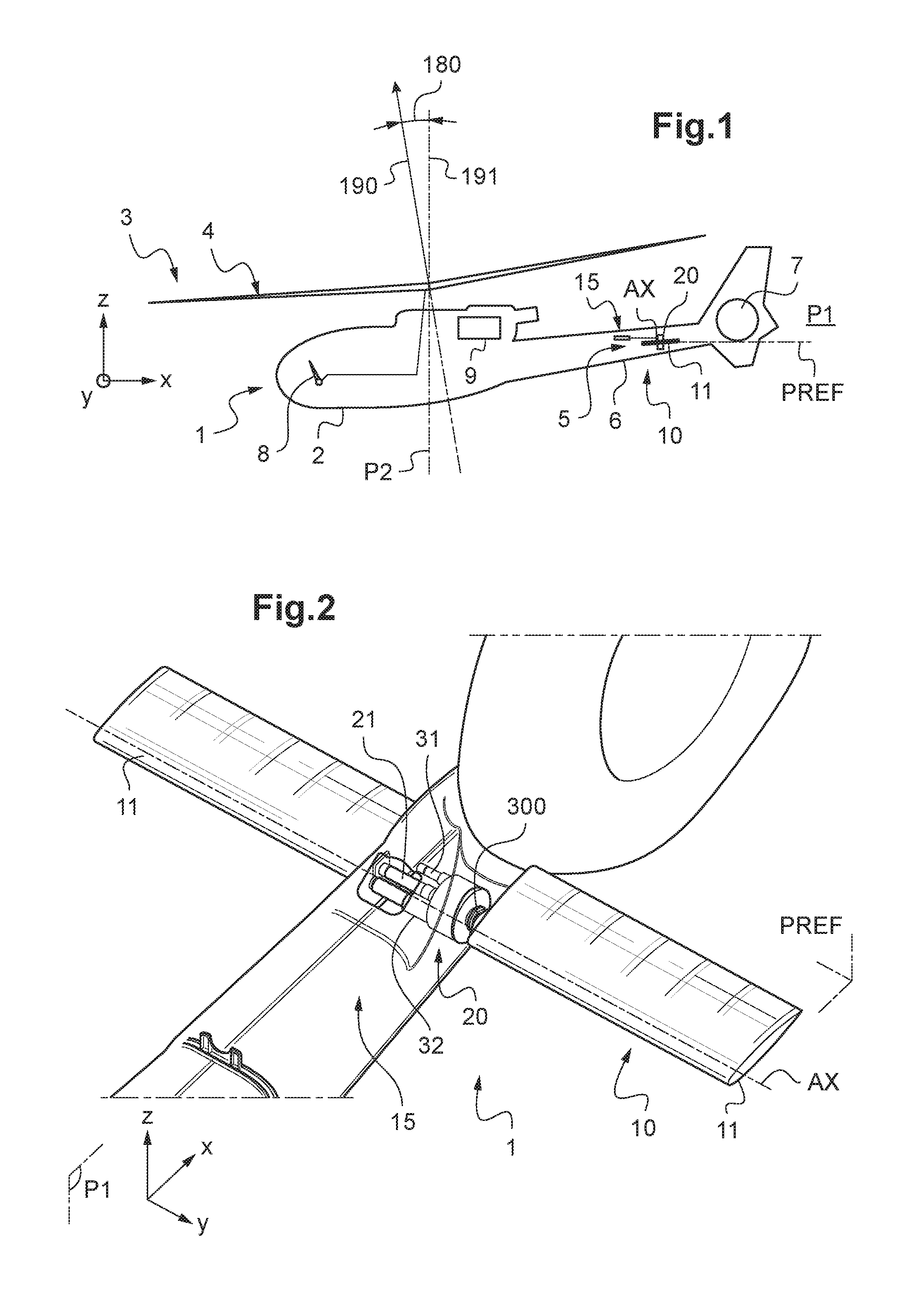
[0151]Three mutually orthogonal directions X, Y, and Z are shown in some of the figures.

[0152]The first direction X is said to be longitudinal. The term “longitudinal” relates to any direction that is substantially parallel to the first direction X.

[0153]The second direction Y is said to be transverse. The terms “lateral” and “transverse” relate to any direction substantially parallel to the second direction Y.

[0154]Finally, the third direction Z is said to be in elevation. The term “in elevation” relates to any direction that is substantially parallel to the third direction Z.

[0155]FIG. 1 shows an aircraft 1 having a fuselage 2. The fuselage 2 extends longitudinally from a nose to a rear end, in elevation from a bottom to a high portion carrying a rotary wing 3, and laterally from a left flank to a right flank.

[0156]By way of example, the aircraft 1 has a rotary wing 3 comprising a main rotor 4 for providing lift and possibly also propulsion. The main rotor 4 is set into rotation b...


PUM


Abstract

A method of controlling a deflection angle of pitching stabilizer means for an aircraft. The method includes a preliminary stage for preparing at least one control relationship delivering a setpoint angle that is to be reached by the deflection angle as a function of at least one flight parameter of the aircraft and of an incidence parameter of the pitching stabilizer means. During an operational stage an operational stage (STP2), a “flight” value is determined for each of the flight parameters, a “setpoint” value is determined for the incidence parameter, a setpoint angle is determined by inputting the flight values and setpoint value into the control relationship, and at least one actuator is actuated in order to cause the deflection angle of the pitching stabilizer means to reach the setpoint angle.

Description

CROSS REFERENCE TO RELATED APPLICATION[0001]This application claims priority to French patent application No. FR 15 00935 filed on May 5, 2015, the disclosure of which is incorporated in its entirety by reference herein.BACKGROUND OF THE INVENTION[0002](1) Field of the Invention[0003]The present invention relates to a method of controlling movable pitching stabilizer means, and to a stabilizer system and to an aircraft applying the method. More particularly, the invention lies in the narrow technical field of means for stabilizing rotorcraft in pitching.[0004](2) Description of Related Art[0005]Conventionally, a rotorcraft comprises, by way of example, a fuselage extending longitudinally from a front end to a rear end on either side of an anteroposterior plane of symmetry, and in a vertical direction from a bottom portion having landing gear to a top portion having a rotary wing. The rotary wing may include at least one main rotor for providing lift and possibly also propulsion.[000...

Claims


Application Information

Patent Timeline
IPC IPC(8): G05D1/08B64C13/16B64C27/82
CPCG05D1/0816B64C27/82B64C2027/8281G05D1/0858B64C13/16
Inventor MOREL, HERVEQUEIRAS, NICOLAS
Owner EUROCOPTER
Why Eureka
Try Eureka