X-ray generating apparatus

a generating apparatus and x-ray technology, applied in the direction of x-ray tubes, vacuum tube vessels/containers/shields, radiation generation arrangements, etc., can solve the problems of reducing the life of the transmission target, the degree of vacuum decreases gradually, and it is not possible to apply a vacuum container to the generating apparatus

Inactive Publication Date: 2016-11-10
SHIMADZU CORP
View PDF0 Cites 4 Cited by
  • Summary
  • Abstract
  • Description
  • Claims
  • Application Information

AI Technical Summary

Benefits of technology

[0018]The rolling elements are balls, and the guide flat surface or the guided flat surface is provided with a regulation mechanism for regulating rolling areas of the individual balls to prevent the balls from deviating from regions respectively set for the balls around the central axis of the electron beam.

Problems solved by technology

Accordingly, there is a problem that the life of the transmission target is reduced by thermal damage due to electron irradiation.
However, if a rubber O-ring is used as described above, the degree of vacuum decreases gradually due to the gas transmission of the O-ring, and the evaporation of vacuum grease and the like.
However, it is not possible to be applied to an x-ray generating apparatus using a seal-off vacuum container such as illustrated in FIG. 9, that is, a sealed x-ray generating apparatus.
It becomes a practical problem.
However, it is difficult to cause the movement with the same force for a long period of time.
In addition, it is not possible either to provide a space for reducing a sliding frictional force in a guide mechanism for regulating the displacement of the moving member with respect to the main body of the vacuum container.

Method used


Image

  • X-ray generating apparatus
  • X-ray generating apparatus
  • X-ray generating apparatus

Examples


Embodiment Construction

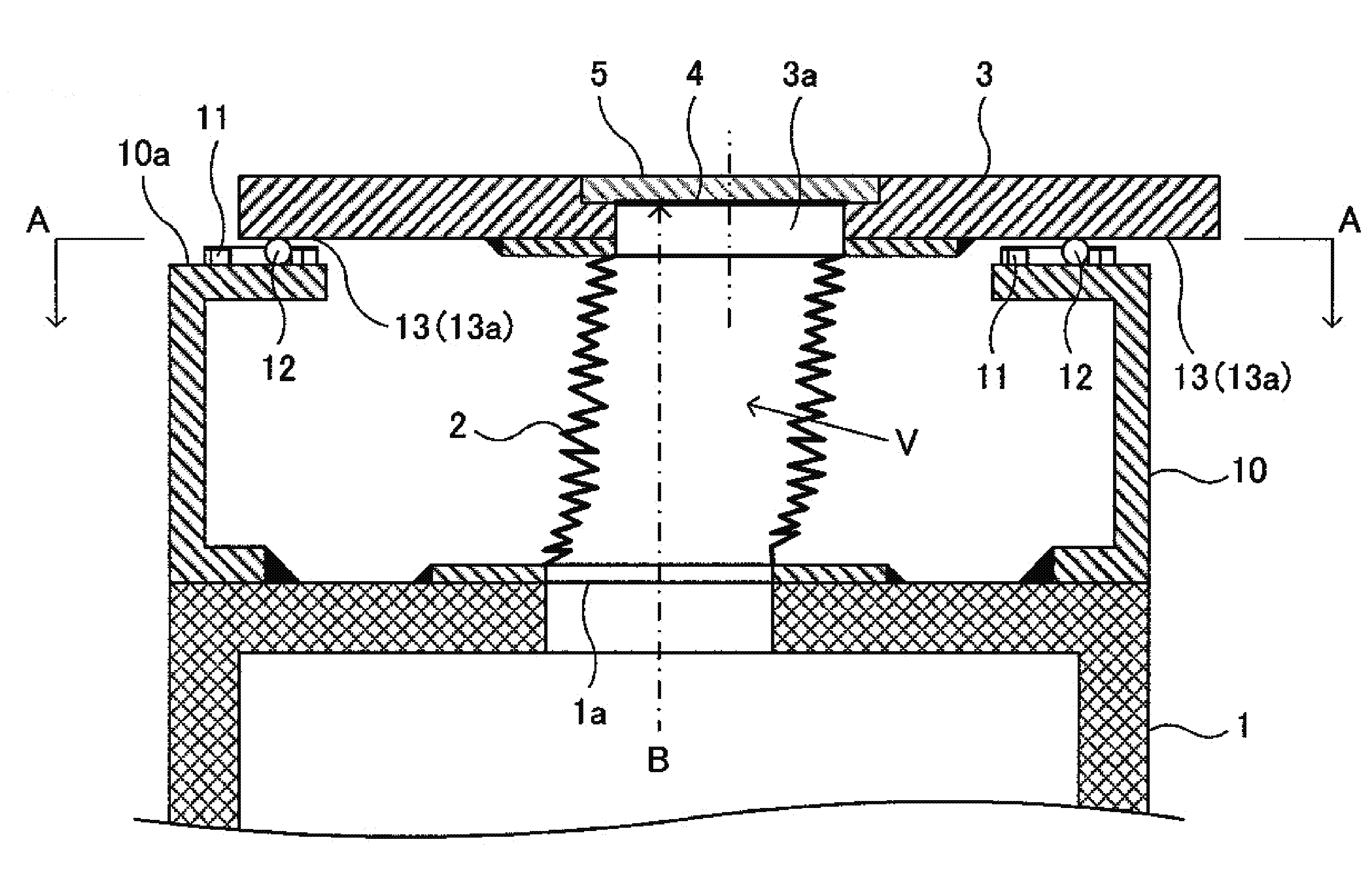
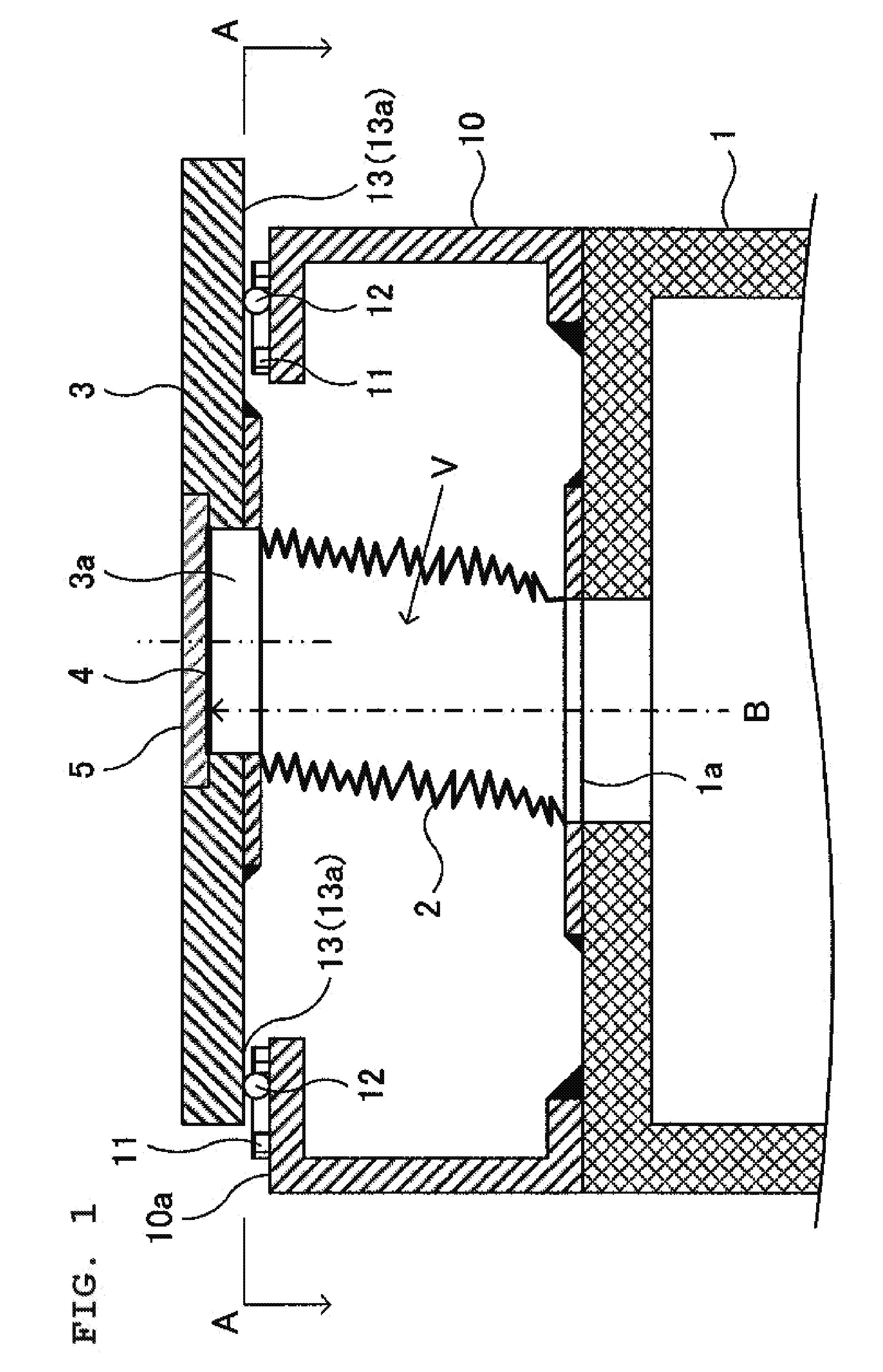
[0034]The present invention is intended to solve the problem by holding a target movably with respect to an electron gun using a vacuum bellows, and reducing a frictional force acting on a guide mechanism for regulating the movement and attitude of the target to maintain the position of an x-ray focal spot constant with rolling contact using a rolling element or contact between a convex curved surface and a flat surface.

[0035]In other words, a moving member provided with the target and an x-ray irradiation window via the vacuum bellows is movably connected to a main body of a vacuum container. Accordingly, the degree of vacuum in the vacuum container is prevented from decreasing. In addition, the guide mechanism for regulating the movement direction and inclination of the target is provided on an outer side of the vacuum container to prevent the x-ray focal spot from moving upon movement of the target. The frictional force acting on a contact portion of the guide mechanism due to th...


PUM


Abstract

An x-ray generating apparatus comprises: a vacuum container having a main body, and a moving member coupled movably and airtightly to the main body via a vacuum bellows; and a guide mechanism, provided on an outer side of the vacuum container, for regulating the movement and inclination of the moving member in an approaching/separation direction with respect to an electron gun. The guide mechanism includes a guide portion where a guide flat surface along a plane orthogonal to a central axis of the electron beam is formed, the guide portion being provided on the main body side, a guided portion where a guided flat surface facing the guide flat surface is formed, the guided portion being provided on the moving member side, and at least three rolling elements placed between the guide flat surface and the guided flat surface.

Description

BACKGROUND OF THE INVENTION[0001]1. Technical Field[0002]The present invention relates to an x-ray generating apparatus.[0003]2. Description of the Related Art[0004]X-ray generating apparatuses of a type that causes electrons to collide with a target in a vacuum container and generates x-rays include one using a reflection target that removes the x-rays in a different direction from the travel direction of the electrons, and one using a transmission target that removes the x-rays in substantially the same direction as the travel direction of the electrons.[0005]Of them, the reflection target generally uses a bulk material. The reflection target is placed, some distance away from an x-ray irradiation window for removing x-rays from the vacuum container to the outside, in the rear of the container. In contrast, the transmission target generally adopts a structure of being laminated and formed integrally with the x-ray irradiation window. Accordingly, an x-ray focal spot is at the near...

Claims


Application Information

Patent Timeline
Patent Type & Authority Applications(United States)
IPC IPC(8): H01J35/24H01J35/18H01J35/08
CPCH01J19/54H05G1/04H01J19/64H01J5/04H05G1/02A61B2560/0406H01J2235/163H01J35/16H01J5/02A61B6/44H01J5/48H01J2235/16A61B6/40H01J37/16H01J35/101H01J35/186H01J35/20H01J35/28
Inventor MIYAOKA, AKIHIRO
Owner SHIMADZU CORP
Why Eureka
Try Eureka