
Method and apparatus for increasing heat dissipation capacity of a din rail mounted enclosure

a technology of heat dissipation capacity and din rail, which is applied in the field of electric devices, can solve the problems of increasing the life expectancy of industrial embedded products, power consuming electronic components generating more internal heat rise than the enclosure is capable of dissipating on its own, and modern electronic components produce excessive amounts of heat during operation

Active Publication Date: 2016-11-10
SCHNEIDER ELECTRIC USA INC
View PDF5 Cites 17 Cited by
  • Summary
  • Abstract
  • Description
  • Claims
  • Application Information

AI Technical Summary

Benefits of technology

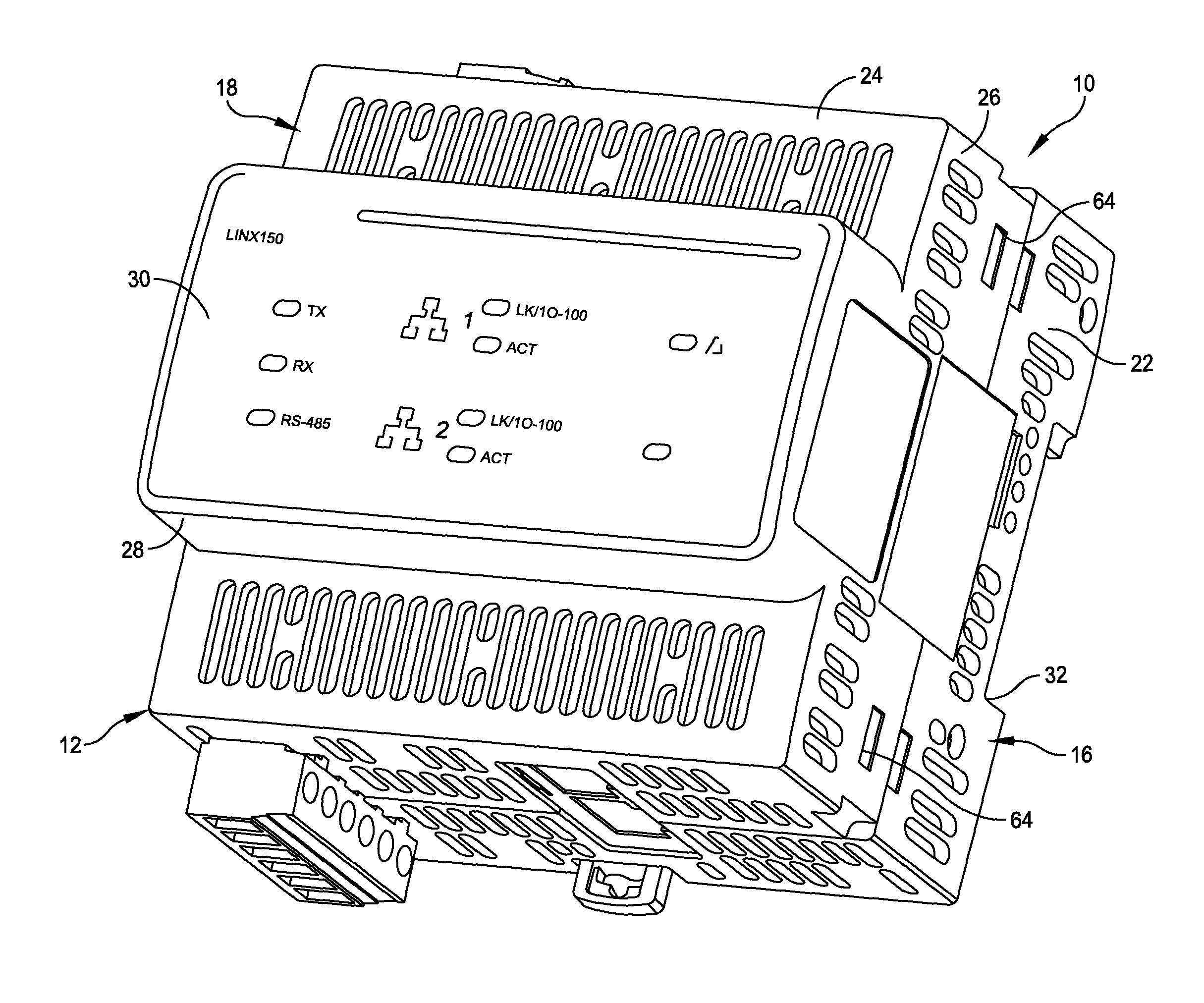
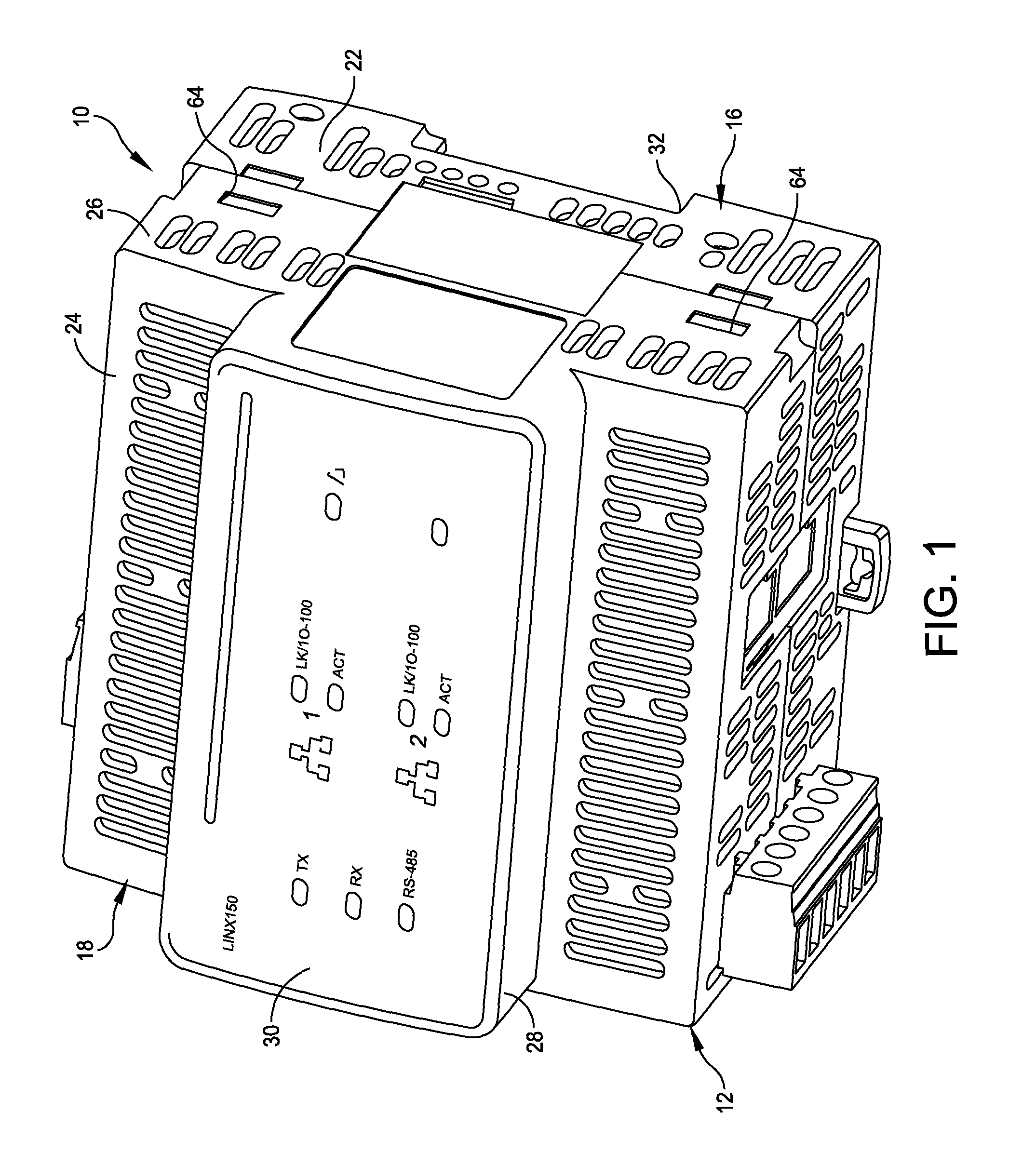
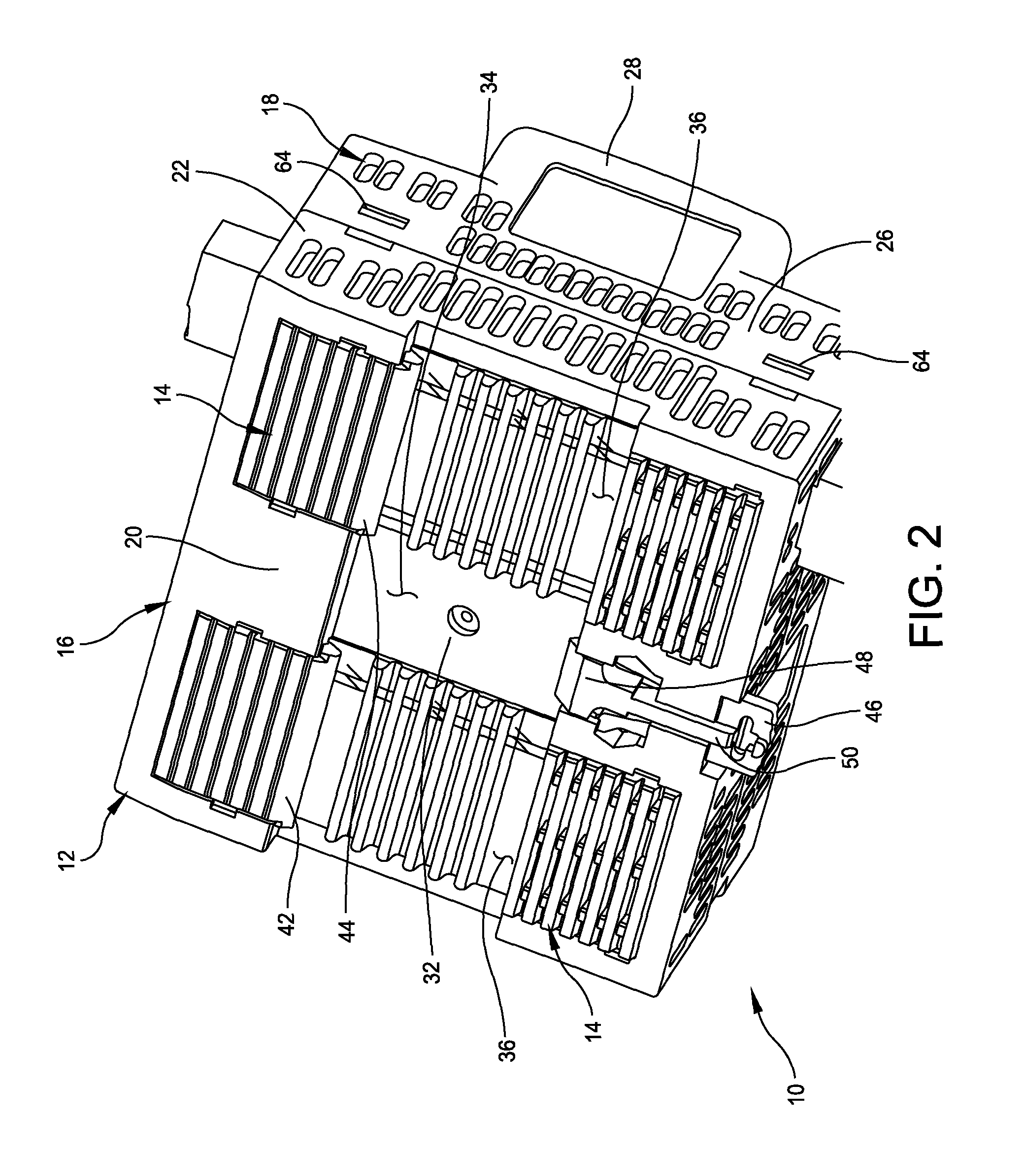
The present disclosure describes a mounting enclosure assembly and a method for mounting electronic components onto a DIN rail. The assembly includes a mounting bracket with a heat sink and a retainer for securing the electronic component. The assembly also includes a thermal bonding material that securely attaches the electronic component to the heat sink located within the mounting bracket. The thermal bonding material may include a flexible sheet, such as a thermal foam pad, which wraps around the edge of the electronic component. The heat sink may engage the DIN rail to hold the mounting bracket in place. The technical effects include improved cooling for electronic components and simplified installation onto a DIN rail.

Problems solved by technology

Modern electronic components produce excessive amounts of heat during operation.
One of the main design challenges associated with these products is thermal management.
Far too often, power consuming electronic components generate more internal heat rise than the enclosure is capable of dissipating on its own.
However, industrial embedded products typically have long life expectancies (up to ten years) and must be rated to work in temperature environments from −25 to +70 degrees Celsius (° C.) and cooling fans cannot reliably meet these requirements.

Method used


Image

  • Method and apparatus for increasing heat dissipation capacity of a din rail mounted enclosure
  • Method and apparatus for increasing heat dissipation capacity of a din rail mounted enclosure
  • Method and apparatus for increasing heat dissipation capacity of a din rail mounted enclosure

Examples


Embodiment Construction

[0025]As discussed above, traditional heat sinks suffer from several disadvantages, such as being increasingly large, heavy and costly. Accordingly, there is a need for a more efficient device, system and method of heat dissipation that is easier to construct and assemble, and takes advantage of the heat dissipating structure on which the device attaches. The assembly of the present disclosure includes the functionality of prior designs with enhanced performance.

[0026]The systems and methods disclosed herein enable DIN rail mountable enclosures to utilize the readily available metal mass of the DIN rail to function as a greater heat sink device. The systems and methods embody a combined DIN rail mounting bracket and heat sink assembly integrated with multiple printed circuit board assemblies (PCBAs), thermal bonding material, and a plastic DIN rail mountable enclosure. The combined DIN rail mounting bracket and heat sink device serves many purposes, including: 1) a DIN rail mounting...


PUM


Abstract

A mounting enclosure assembly is configured to mount electronic components onto a DIN rail. The mounting enclosure assembly includes a mounting bracket including a body having at least one elongate slot configured to receive an edge of the electronic component therein. The mounting enclosure assembly further includes a heat sink secured to the mounting bracket. The heat sink includes a mounting configuration configured to secure the heat sink and the mounting bracket to the DIN rail. The mounting enclosure assembly further includes a thermal bonding material disposed within the slot to secure the electronic component to the body of the mounting bracket within the slot. Other embodiments of the mounting enclosure assembly are further disclosed.

Description

BACKGROUND[0001]1. Field of Disclosure[0002]The present disclosure relates generally to the field of electronics and, more particularly, to devices and methods that remove or dissipate heat from electronic components.[0003]2. Discussion of Related Art[0004]Modern electronic components produce excessive amounts of heat during operation. To ensure that the components do not overheat, system designers attach convective heat sinks to cool these components, by providing an efficient heat transfer path from the devices to the environment. A typical convective heat sink is designed to transfer heat energy from the high temperature component to lower temperature of the surrounding air. Such typical heat sinks attach to the components through a base and include fins or pins to increase the surface area of the heat sink within a given space.[0005]Within rack enclosures, embedded systems demand more and more features running on faster processors and must be enclosed in smaller packages. One of...

Claims


Application Information

Patent Timeline
Patent Type & Authority Applications(United States)
IPC IPC(8): H05K7/20H05K7/14
CPCH05K7/1474H05K7/20472H05K7/18
Inventor WILLIAMS, JEFFREY SCOTTMAYES, GARY LENNFARRELL, MICHAEL JAMES
Owner SCHNEIDER ELECTRIC USA INC
Learn More