Instrument for use with a polyaxial bone anchoring device and system including the instrument and a polyaxial bone anchoring device

a polyaxial bone and anchoring device technology, applied in the field of polyaxial bone anchoring device system, can solve the problem of too low pressure element, achieve precise adjustment of desired friction force, facilitate handling during surgery, and facilitate the effect of facilitating the use of the instrumen

Active Publication Date: 2016-11-17
BIEDERMANN TECH GMBH & CO KG
View PDF3 Cites 2 Cited by
  • Summary
  • Abstract
  • Description
  • Claims
  • Application Information

AI Technical Summary

Benefits of technology

[0007]In-situ placement of a receiving part onto a bone anchoring element that has been already inserted into a bone or a vertebra may be advantageously facilitated by mounting the receiving part and a pressure element onto a head of the bone anchor with a low insertion force. However, if the insertion force is low, a pre-stress exerted on the head of the bone anchoring element by the receiving part and the pressure element may be too low for the further procedure of aligning the receiving part for inserting a rod.
[0008]Embodiments of the invention provide an instrument for use with a polyaxial bone anchoring device and a system of an instrument and an improved polyaxial bone anchoring device that facilitates handling during surgery.
[0009]In one or more embodiments, an instrument is provided that allows adjusting a friction force exerted on a head of a bone anchoring element in an easy manner during surgery. In particular, the instrument, in connection with a polyaxial bone anchoring device, allows an operator to manually adjust the friction force on the head manually by actuating an actuating member of the instrument with one hand while holding the receiving part with a holding member held by the other hand of the operator. Pivoting the receiving part relative to the bone anchor element with the holding member gives the surgeon immediate feedback of the friction force acting on the head. The instrument permits a precise adjustment of the desired friction force on the head by sensing the friction force with the surgeon's hands.
[0010]The instrument may be particularly useful for a polyaxial bone anchoring element of the bottom loading type, where the head of the bone anchoring element is inserted into the receiving part from a bottom end thereof. The receiving part can be placed on the head of the bone anchoring element in-situ, after a shank of the bone anchoring element has already been inserted into (i.e., anchored to) a bone. Hence, in one or more embodiments, an instrument for use with an in-situ type bottom loading bone anchoring element is provided, where the friction force acting on the head can be adjusted in-situ on a patient.
[0011]The holding member of the instrument may be connected to the receiving part in a positive-fit manner where a surface of the receiving part cooperates with a surface of the holding member to prevent rotation between the holding member and the receiving part.
[0012]The actuating member may be connectable to the holding member only in a specific position (e.g., orientation) relative to the holding member. In this position, an engagement portion of the actuating member is substantially aligned with an engagement portion of a clamping element of the polyaxial bone anchoring device such that the clamping element can be easily engaged by the engagement portion of the actuating member. Thereby, the procedure of locating the clamping element with the instrument is facilitated and the actuation of the clamping element can be performed quickly. Through use of the clamping element, the friction force on the head of the anchoring element can be increased by rotating the clamping element in one direction and can be decreased by rotating the clamping element in an opposite direction. The procedure of aligning a plurality of receiving parts for inserting a rod is considerably simplified by manual adjustment of the frictional clamping of the head before final locking.

Problems solved by technology

However, if the insertion force is low, a pre-stress exerted on the head of the bone anchoring element by the receiving part and the pressure element may be too low for the further procedure of aligning the receiving part for inserting a rod.

Method used


Image

  • Instrument for use with a polyaxial bone anchoring device and system including the instrument and a polyaxial bone anchoring device
  • Instrument for use with a polyaxial bone anchoring device and system including the instrument and a polyaxial bone anchoring device
  • Instrument for use with a polyaxial bone anchoring device and system including the instrument and a polyaxial bone anchoring device

Examples


Embodiment Construction

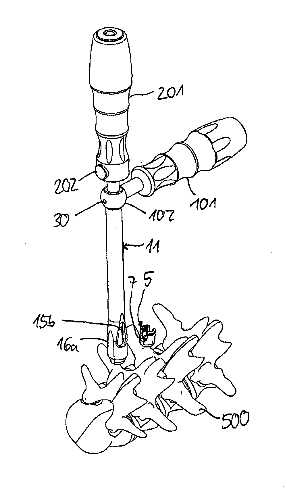
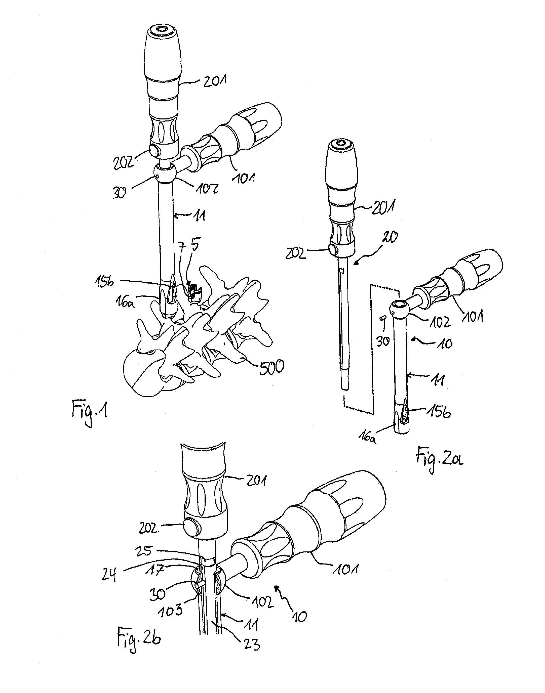
[0029]Referring to FIGS. 1 to 2b, and instrument according to an embodiment includes a first member 10 and a second member 20 insertable into the first member 10. The first member 10 is configured to engage a receiving part 5 of a polyaxial bone anchoring device. In FIG. 1, the receiving part 5 is pivotably connected to a bone anchoring element that has been already inserted into a pedicle of a vertebra 500 prior to being connected to the receiving part 5. As described more fully below, a portion of the second member 20 is configured to engage and rotate a clamping element 7 provided in the receiving part 5.

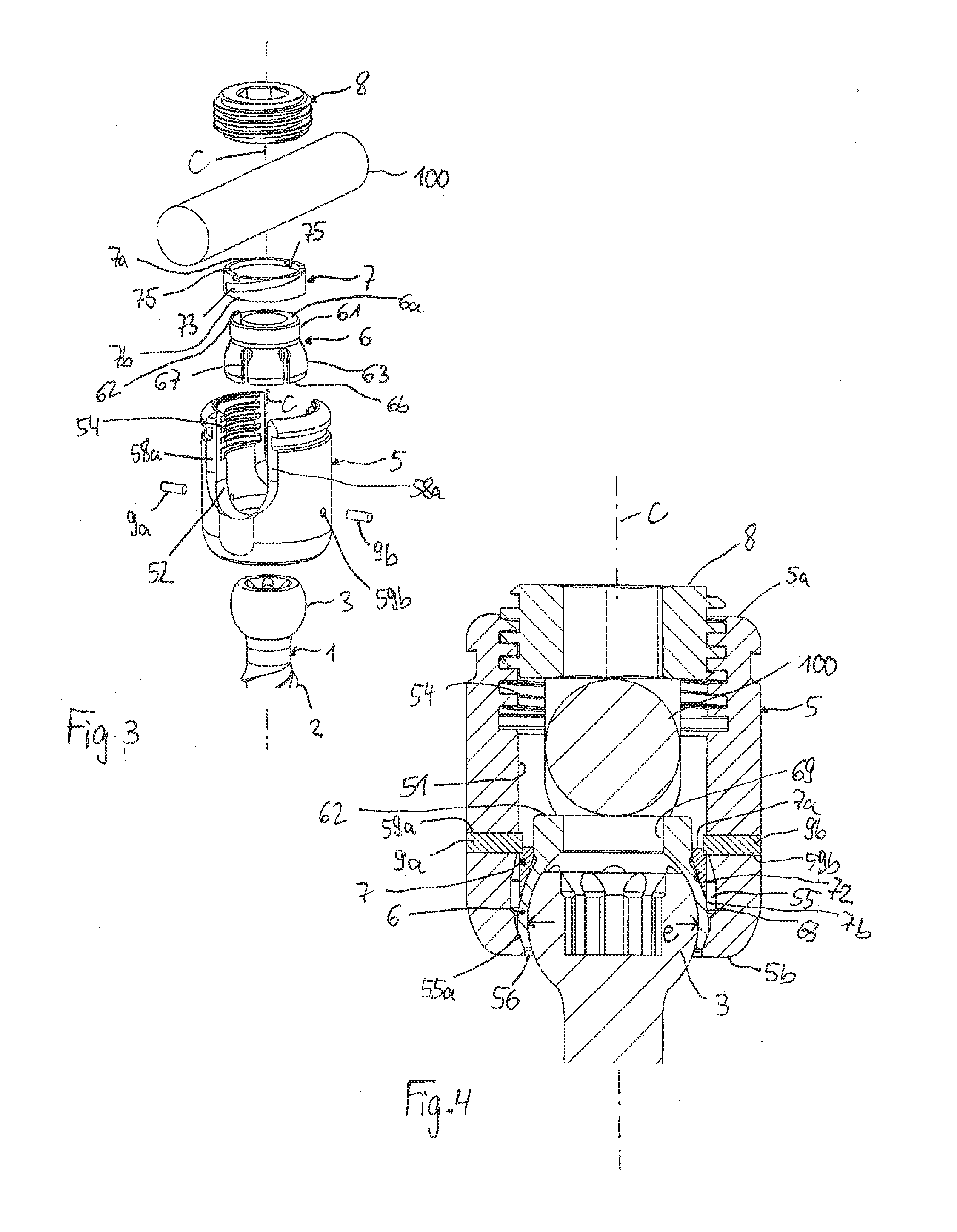
[0030]Next, an embodiment of a polyaxial bone anchoring device that is used with the instrument will be described with reference to FIGS. 3 and 4. The polyaxial bone anchoring device includes a bone anchoring element 1, for example in the form of a bone screw having a threaded shaft 2 for anchoring to a bone and a head 3 that may be sphericalically segment-shaped. The bone anchor...


PUM


Abstract

An Instrument for use with a polyaxial bone anchoring device is provided, where the polyaxial bone anchoring device includes a receiving part for receiving a rod and for accommodating a head of a bone anchoring element. The head can be clamped by exerting a pressure force onto it via a clamping element and the pressure force can be adjusted using the instrument. The instrument includes a first member having a first engagement portion configured to engage the receiving part in a positive-fit manner. The instrument also includes a second member having a front end and a second engagement portion configured to engage the clamping element and apply torque to the clamping element. In a first configuration, the second member is axially displaceable along a longitudinal axis relative to the first member and is restricted from rotational movement. In a second configuration, the second member is rotatable with respect to the first member.

Description

CROSS-REFERENCE TO RELATED APPLICATIONS[0001]The present application claims the benefit of U.S. Provisional Application Ser. No. 62 / 160,474, filed May 12, 2015, the contents of which are hereby incorporated by reference in their entirety, and claims priority from European Patent Application EP 15 167 425.6, filed May 12, 2015, the contents of which are hereby incorporated by reference in their entirety.BACKGROUND[0002]1. Field[0003]The present disclosure relates to an instrument for use with a polyaxial bone anchoring device and to a system including the instrument and a polyaxial bone anchoring device. The polyaxial bone anchoring device includes a receiving part for receiving a rod and for accommodating a head of a bone anchoring element. The head can be clamped by exerting a pressure onto it via a clamping element. The instrument includes a first member and a second member displaceable relative to the first member. The first member is configured to engage the receiving part in a ...

Claims


Application Information

Patent Timeline
Patent Type & Authority Applications(United States)
IPC IPC(8): A61B17/70A61B17/88
CPCA61B17/8891A61B17/7082A61B17/7002A61B17/7074A61B17/862A61B17/8625A61B2017/00831A61B2017/564A61B2017/8655A61B17/7037
Inventor BIEDERMANN, LUTZ
Owner BIEDERMANN TECH GMBH & CO KG
Why Eureka
Try Eureka