Pin filter

a technology of a filter and a pin, applied in the field of fluid filters, can solve the problems of clogging of filter elements closure, corrosion or galling, etc., and achieve the effect of preventing fluid communication

Active Publication Date: 2016-11-17
PARKER INTANGIBLES LLC
View PDF10 Cites 16 Cited by
  • Summary
  • Abstract
  • Description
  • Claims
  • Application Information

AI Technical Summary

Benefits of technology

[0009]The bowl may include an inlet port fluidly connectable to one of the opposed fluid transfer passages and an outlet port fluidly connectable to the other of the opposed fluid transfer passages, and may further a seal element disposed between the bowl and the cover element that within the bowl fluidly separates the inlet port from the outlet port, preventing fluid communication within the bowl between the inlet port and outlet port.

Problems solved by technology

During use the filter element may become clogged to the point that is causes a problem in the system, such as inadequate flow to components downstream of the filter, excessive pressure upstream of the filter element, and / or damage to the filter element allowing the accumulated contaminants to flow to components downstream of the filter element.
Such replacement can be extremely difficult when the closure, such as a threaded closure, has suffered corrosion or galling due to repeated removal / reattachment or due to the environment of use.
For example, filter assemblies used in oil drilling applications are often subjected to air and moisture heavy with salts, causing corrosion of the filter assembly components.
In these situations, great force and time can be necessary simply to remove the housing, or in a worse case, the housing and associated bowl coupling, such as threading, may become irreparably damaged in the removal process requiring replacement of the entire filter assembly including the bowl and housing.

Method used


Image

  • Pin filter
  • Pin filter
  • Pin filter

Examples


Embodiment Construction

[0050]The principles of the present disclosure have particular application to oil and gas fluid transfer systems, such as in fluid transfer systems of oil drilling rigs. As used herein, the term “fluid” refers to liquid, gas, or any combination thereof. Of course, the principles of the present disclosure may also be useful in applications other than oil and gas applications, such as in other fluid transfer operations, such as for moving water, alcohol, oxygen, etc. For example, the filter assembly of the present disclosure may be suitable in operations where galling of threaded components leads to difficulty in performing maintenance activities on filter assemblies including threaded components having threads exposed to the external environment.

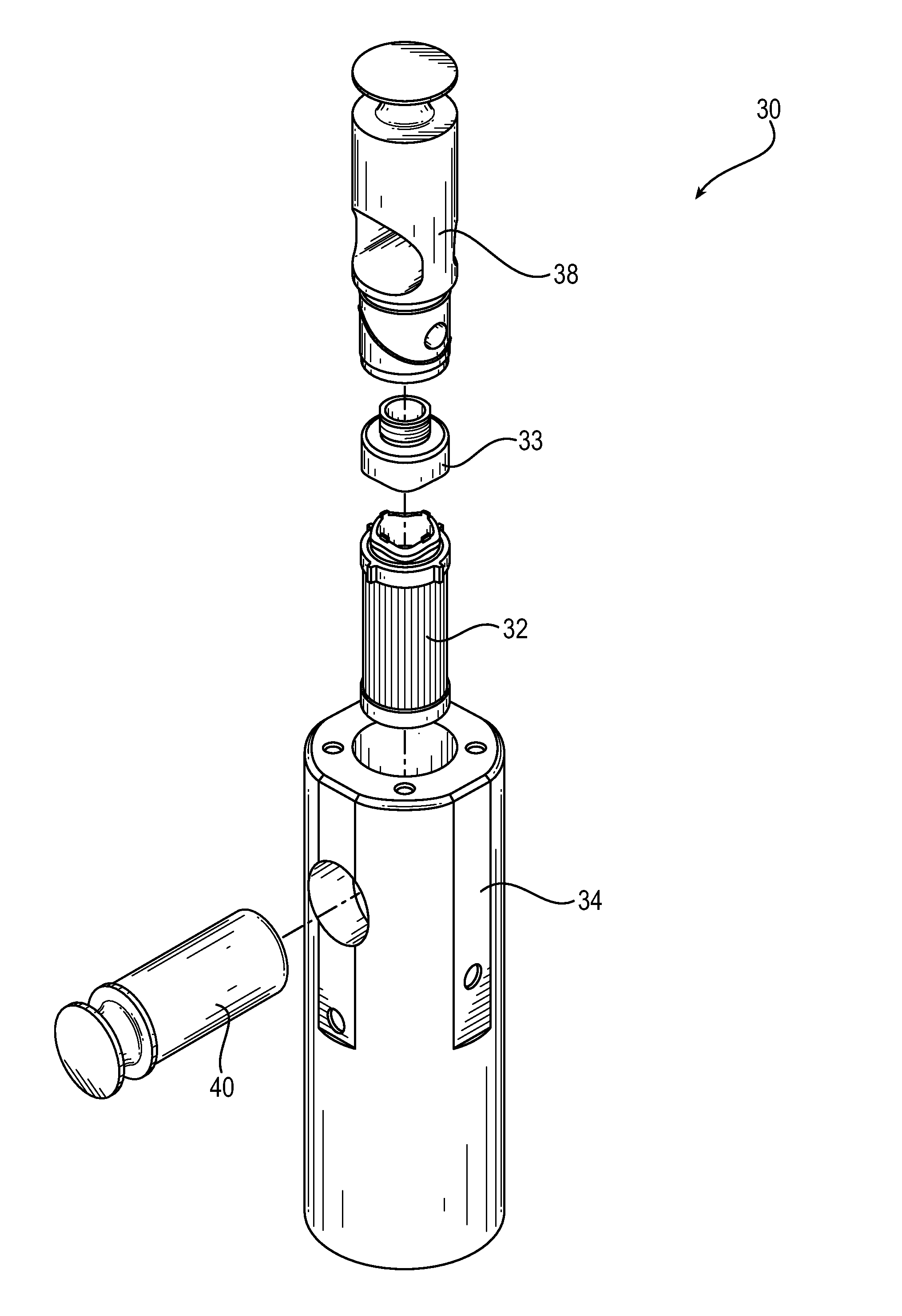
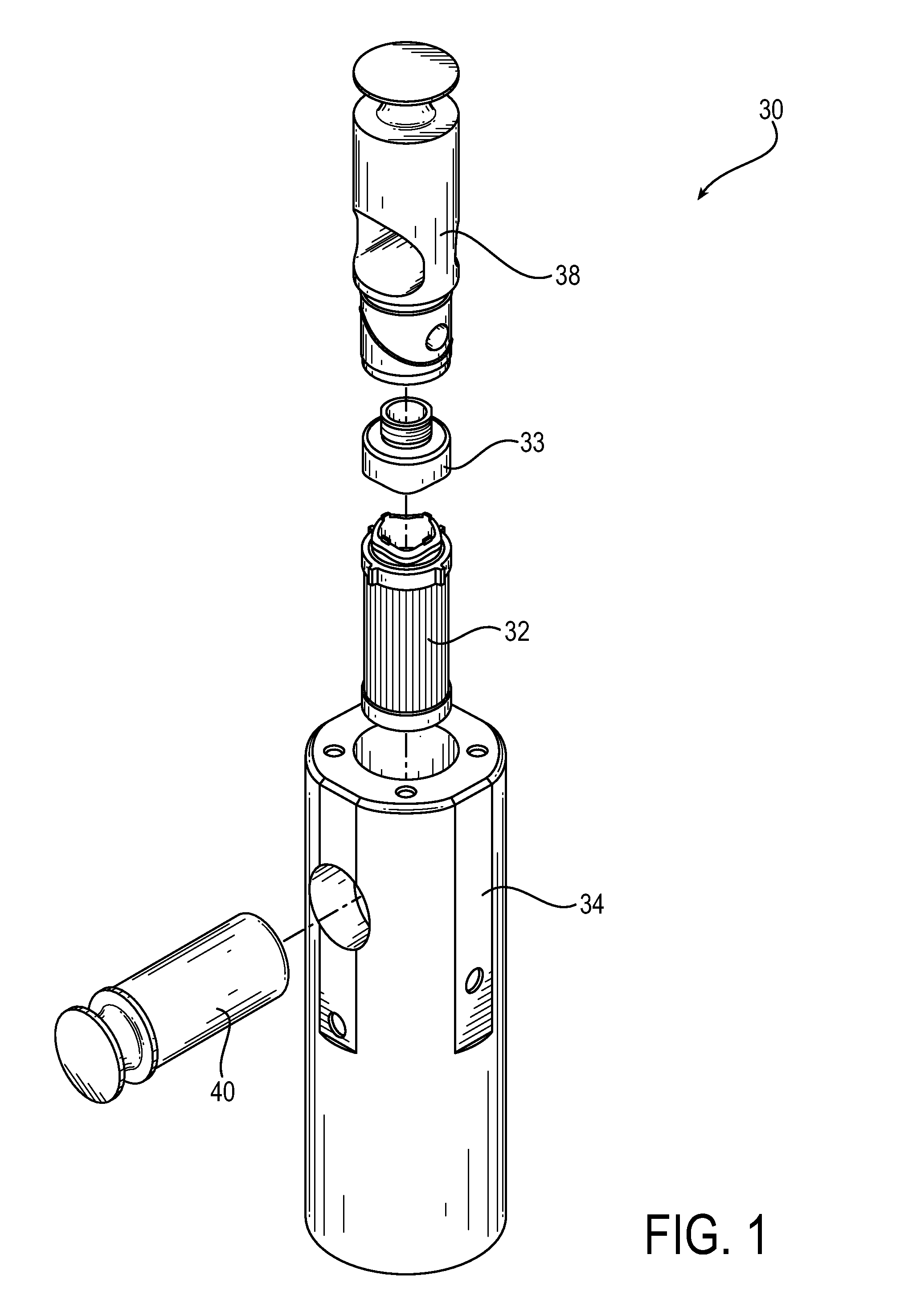
[0051]Turning now to FIG. 1, an exemplary filter assembly 30 is depicted in an exploded view. The filter assembly 30 is configured to be fluidly connected in a fluid transfer system between opposing fluid transfer passages and includes a filt...


PUM

PropertyMeasurementUnit
oblique angleaaaaaaaaaa
pressureaaaaaaaaaa
corrosionaaaaaaaaaa

Abstract

The filter assembly includes a threadless closure system for sealing a filter element of the filter assembly within a bowl of the filter assembly. The bowl is fluidly connectable to opposing fluid transfer passages. The filter element and a cover element connected to the filter element are received into the bowl. The filter element is retained in the bowl via a pin of the filter assembly that engages the cover element. The filter element may be removed and replaced without the unscrewing of threads exposed to an external environment external to the filter assembly during typical use of the filter assembly.

Description

FIELD OF INVENTION[0001]The present invention relates generally to fluid filters and, more particularly, to filters used in oil or gas distribution systems.BACKGROUND[0002]Filter assemblies have been employed in a variety of applications including hydraulic systems, fuel systems and engine lubrication systems. Such assemblies heretofore have used replaceable filter elements that can be installed on a filter head for filtering fluid flowing between inlet and outlet passages in the filter head. The filter element typically is contained within a housing such as a can that can be screwed onto or off of the filter head. In a so-called spin-on filter, the can is discarded along with the filter element. In other arrangements, only the filter element is replaced and the housing is reused.[0003]During use the filter element may become clogged to the point that is causes a problem in the system, such as inadequate flow to components downstream of the filter, excessive pressure upstream of the...

Claims


Application Information

Patent Timeline
Patent Type & Authority Applications(United States)
IPC IPC(8): B01D35/30B01D46/00
CPCB01D35/306B01D46/0005B01D2271/02B01D2201/34B01D2201/305B01D46/008B01D35/31B01D46/0004B01D46/2411B01D46/4227B01D29/15B01D29/96B01D2201/24B01D2201/295B01D2201/306B01D2265/026B01D2265/05B01D2201/4053B01D2201/347B01D46/88B01D27/08B01D35/30
Inventor MARKS, EVANNOE, KEVIN
Owner PARKER INTANGIBLES LLC
Why Eureka
Try Eureka